SAP2000 BIM link for member design
1 How to activate the link
BIM link activation for SAP2000 (v23 and newer)
BIM link activation for SAP2000 (v22 and older)
2 How to use the link
Open the attached project in SAP2000 v22 and run the geometrically nonlinear analysis (GNA)(1) to get results. This type of analysis is predefined in SAP2000 due to the fact that the buckling lengths are not defined in Member application and additional internal forces from the global imperfection ought to be covered in this analysis.
Select the members 42, 43, 44, 48 (2). The connections are automatically exported with selected members.
Go to menu item Tools and choose the IDEA StatiCa plugin (3).
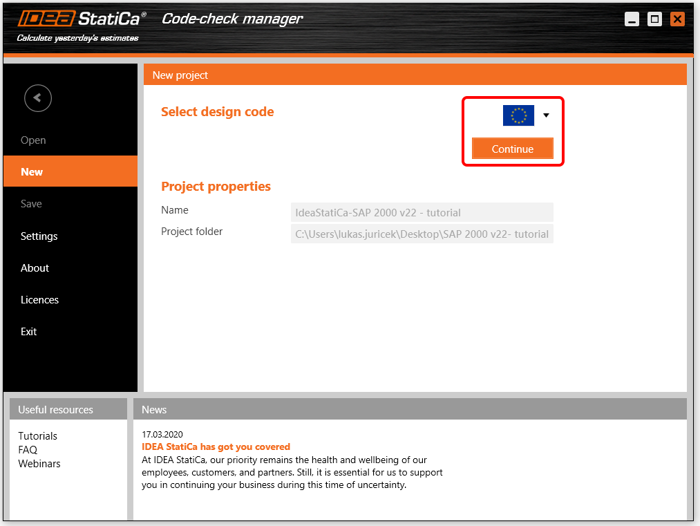
The code check manager pops up and you select the desired Design code (EN).
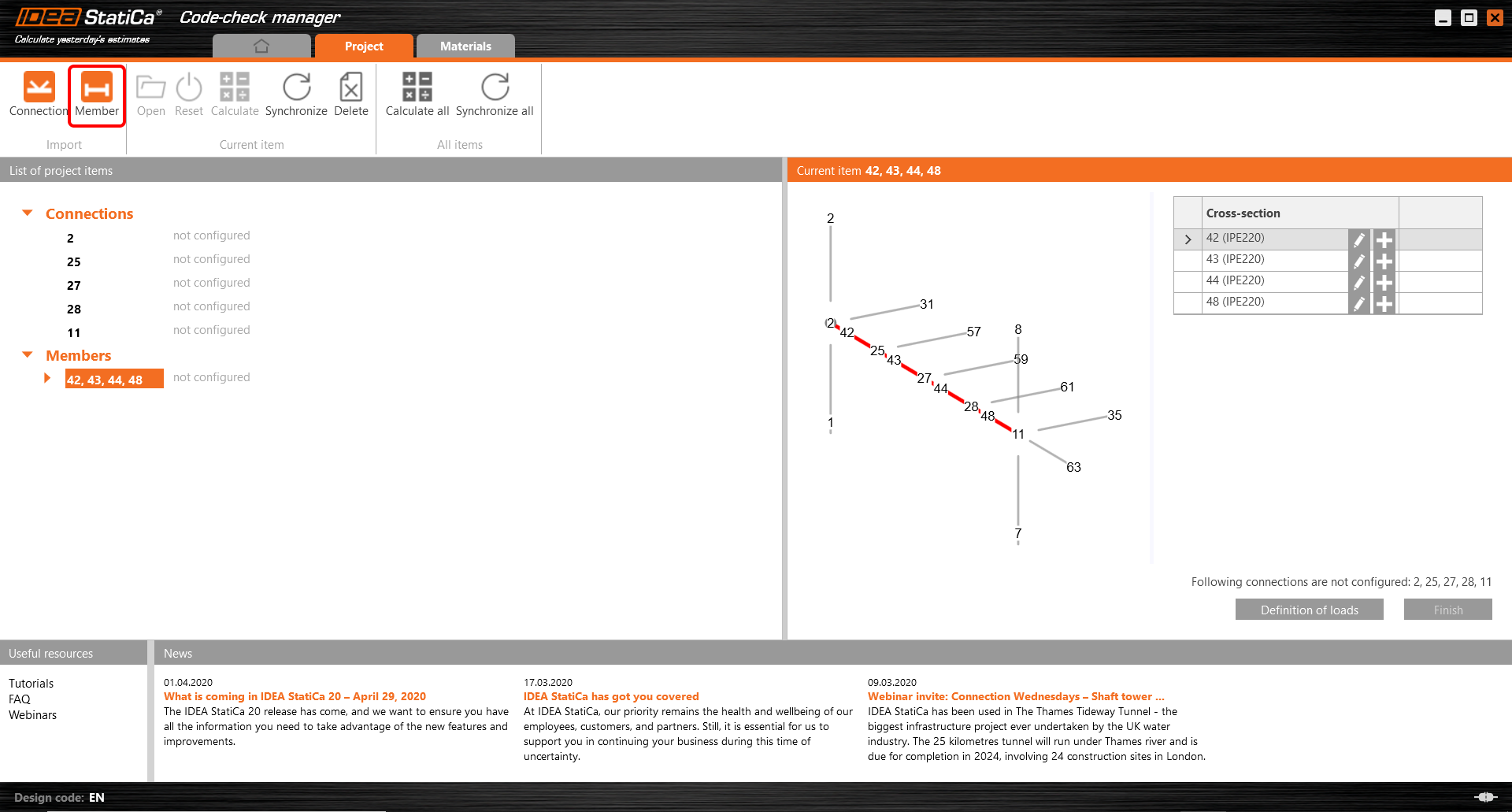
Confirm the selection by pushing Member item. All selected members with related connections are exported to CCM.
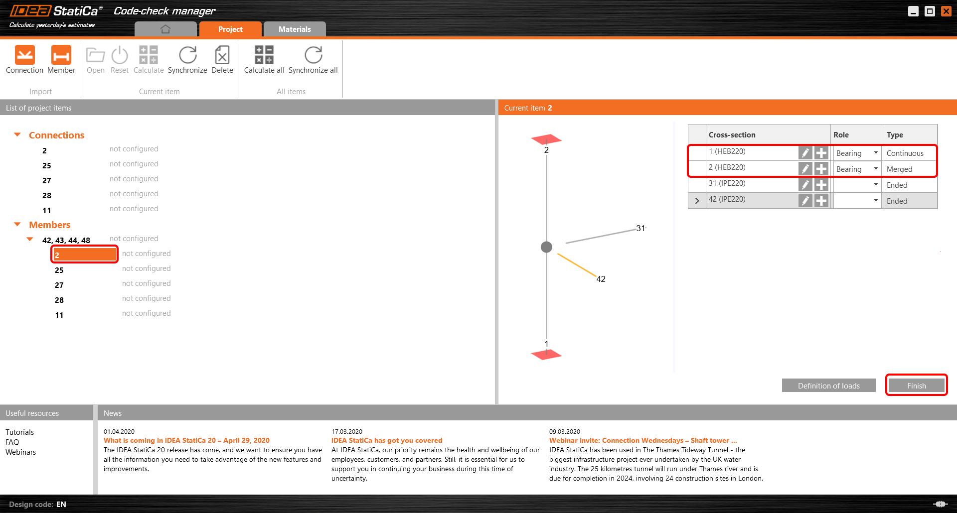
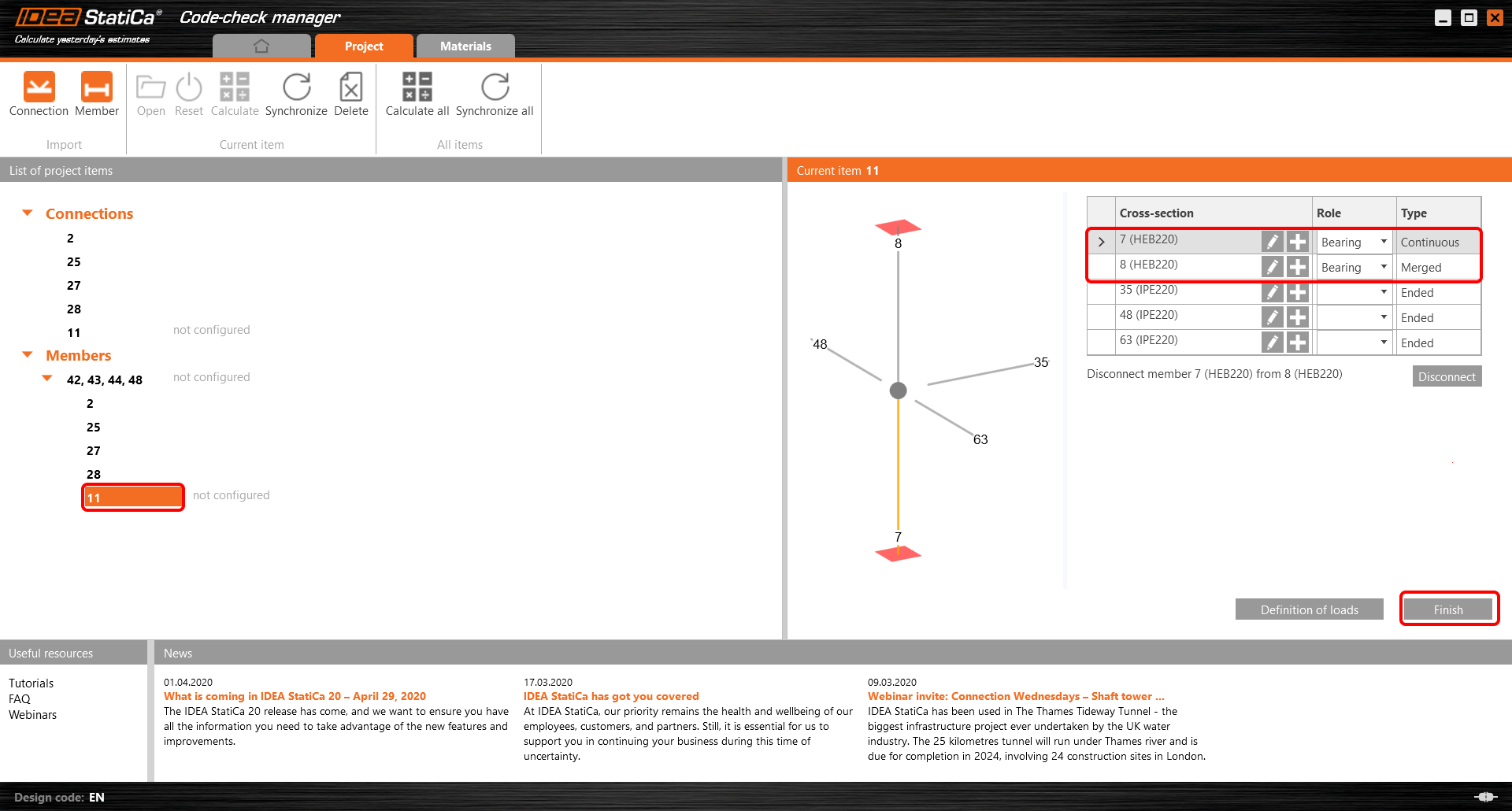
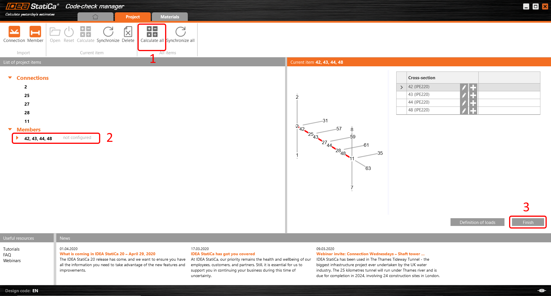
Scroll down the orange arrow under selected members and focus on Connection 2. In the right scene Merge the column consisted of the member 1 and 2. To complete the configurations select the Finish item. Now are all internal forces exported to IDEA StatiCa Connection and the joint is ready for design.
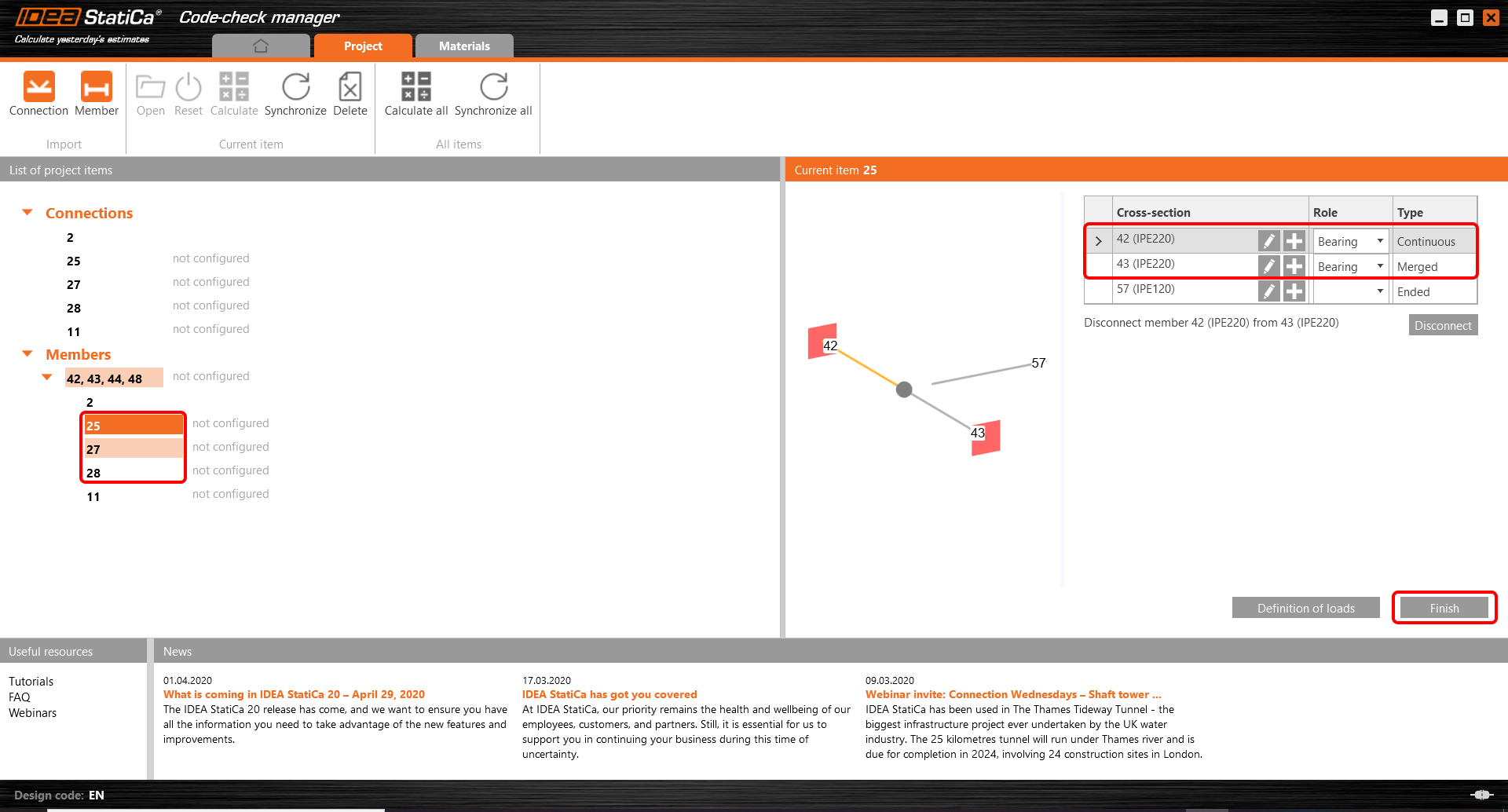
The same procedure with merging and also with finishing the configurations will be performed for joints 25, 27, 28.
The final joint 11 set in the same way as the joint 2.
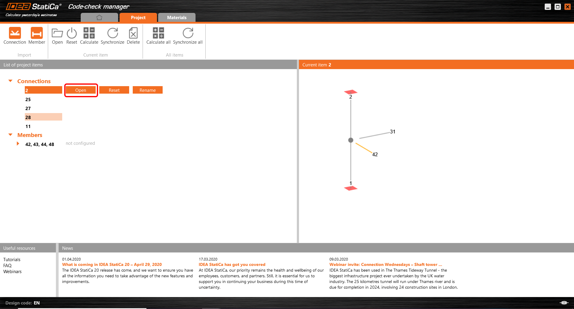
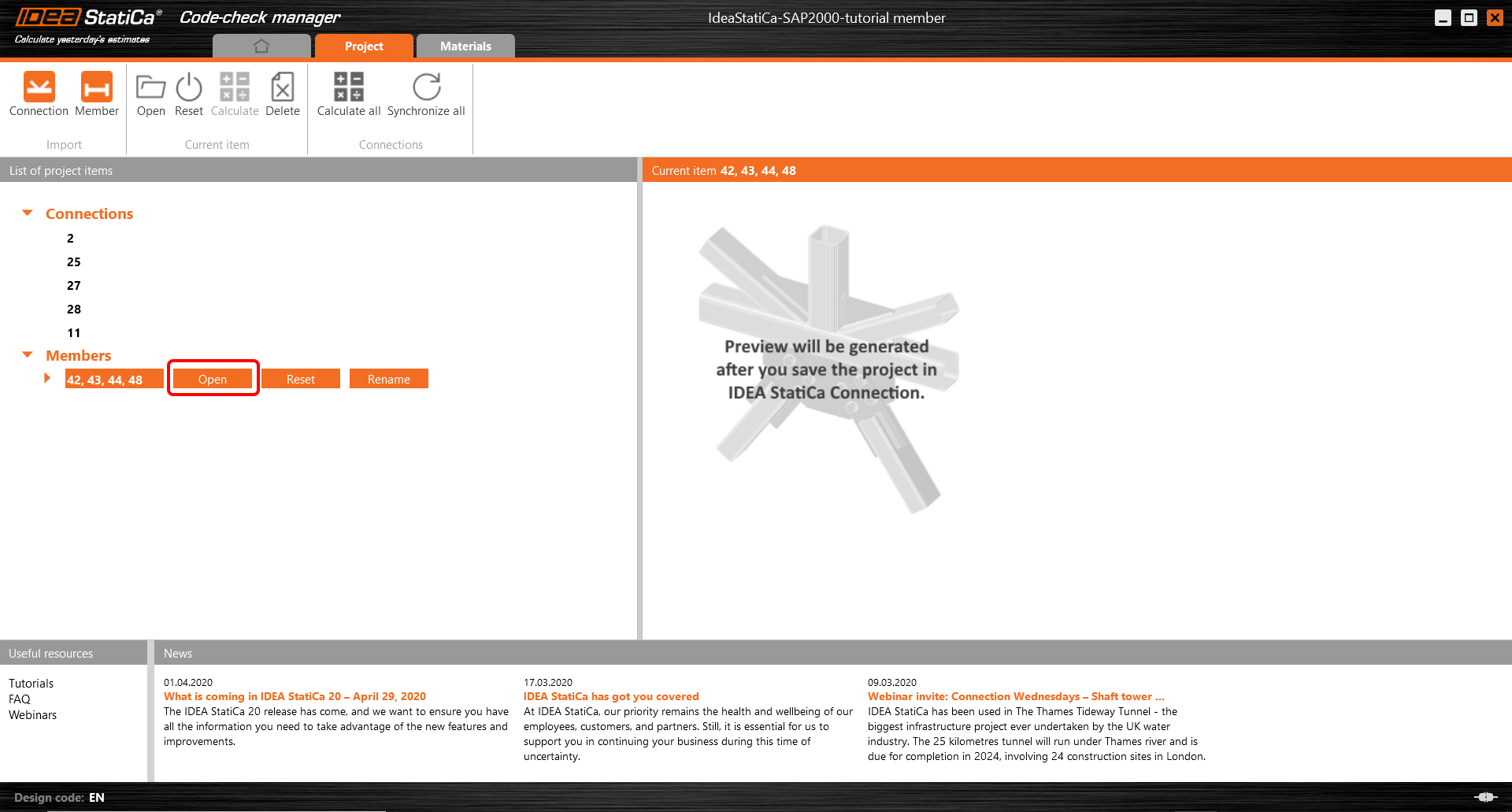
Come back to List of project items - Connections and start with Opening and designing the first joint 2.
3 Design
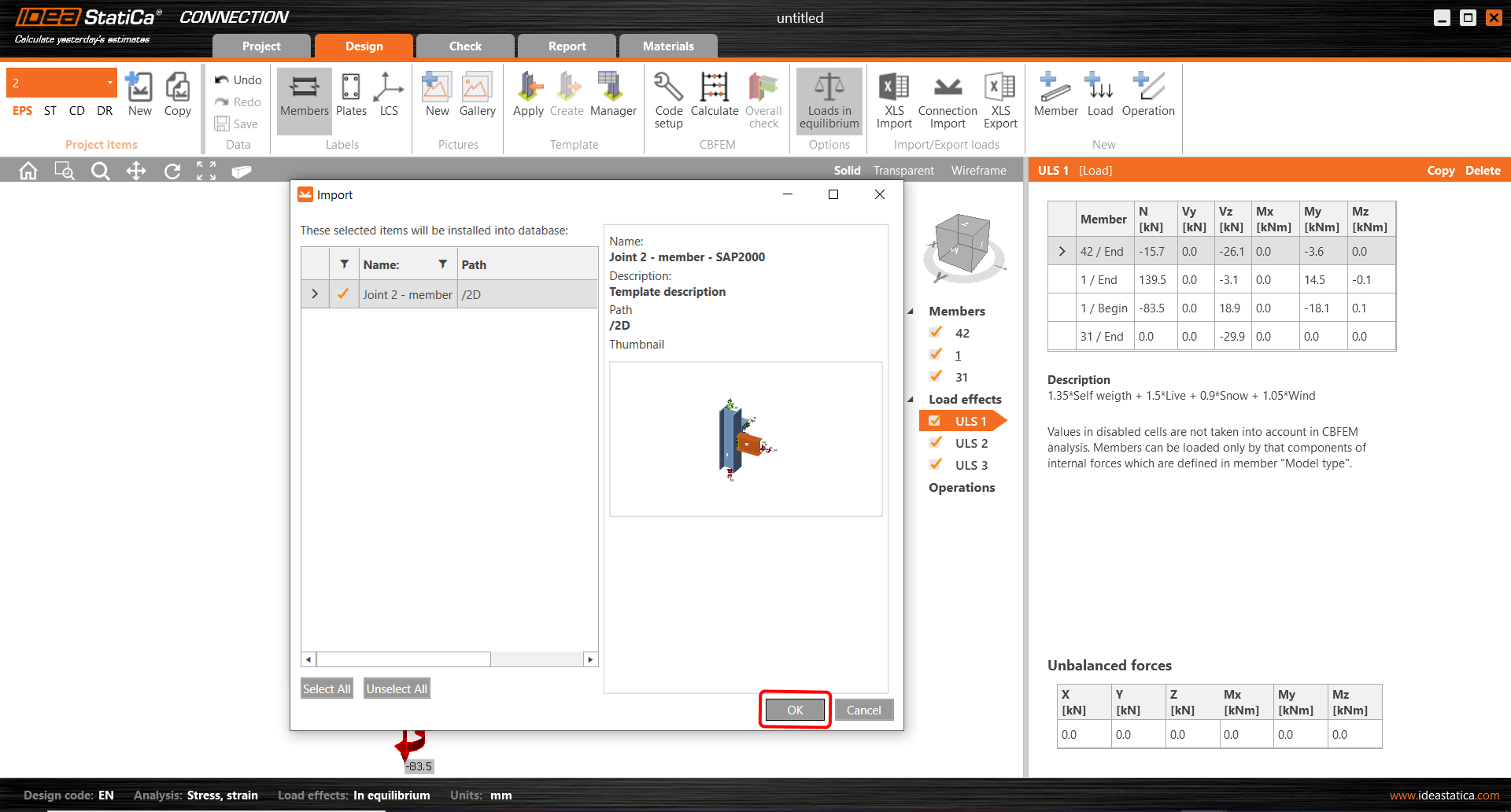
To speed up the process of creating the joints you can use the templates. All the joints have been designed and saved in the attached folder (Rar). Go through the Manager (1) and use Import (2) for uploading all joints. All three joints will be defined in the same procedure (3). For joint 2 use the template Joint2_member-SAP2000.exp.
Confirm the selection by OK item.
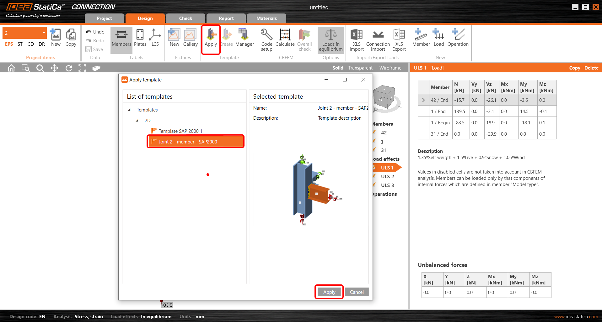
In the ribbon, select Apply and use the imported joint.
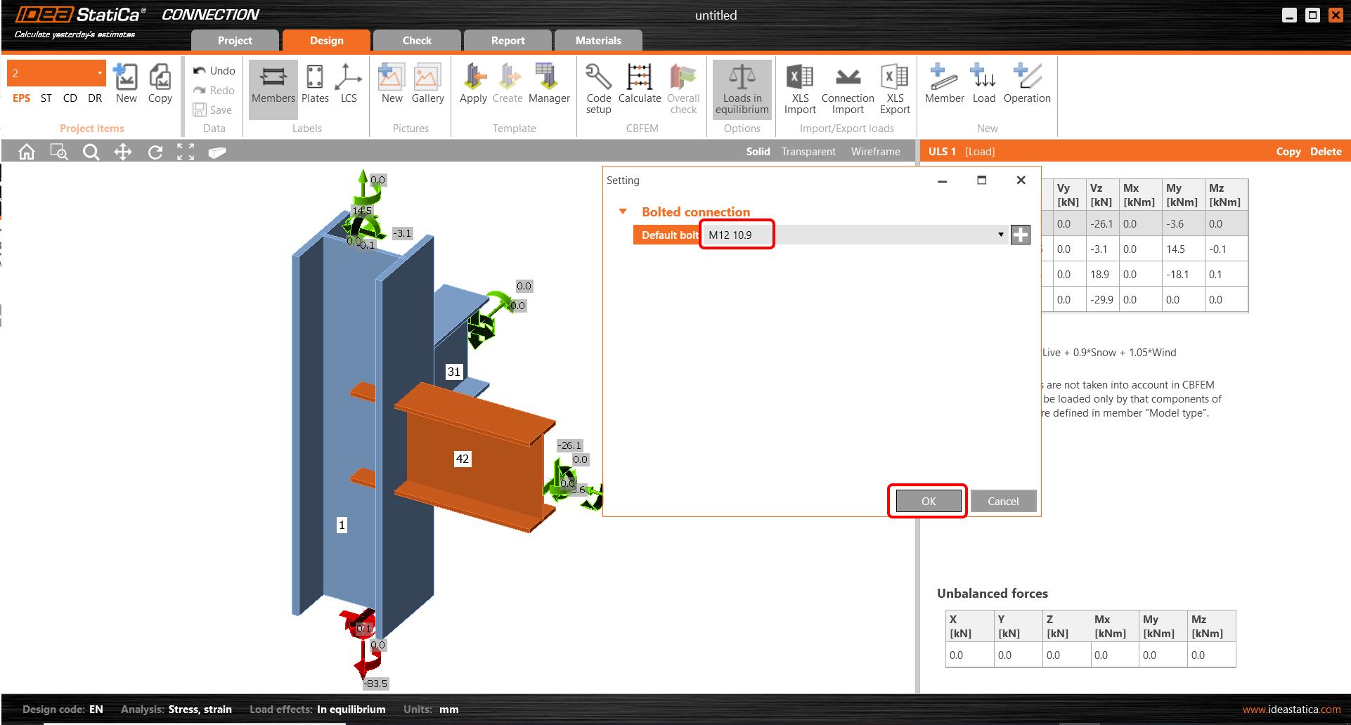
The bolts are set for all joints the same. Use the Bolt M12 10.9.
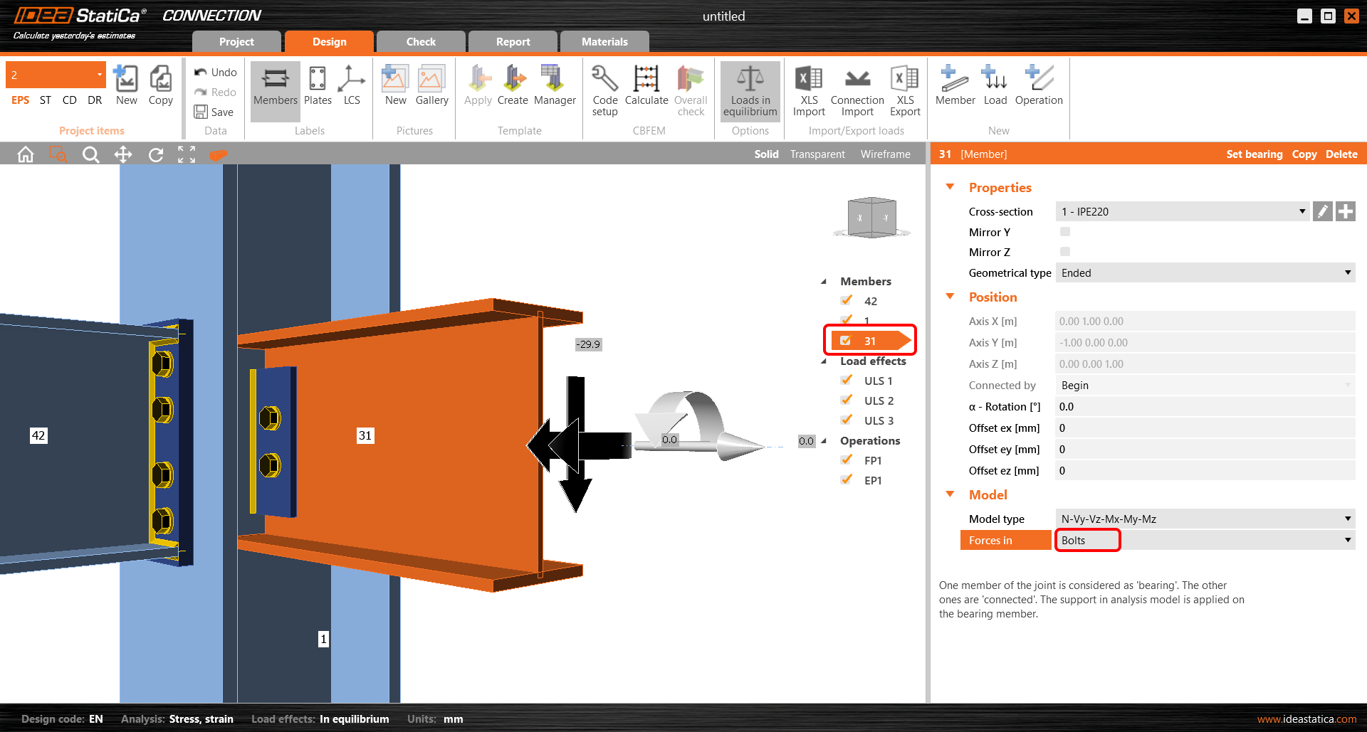
Member 31 is connected by manufacturing operation Fin plate where the position of acting shear force in the Bolts needs to be changed.
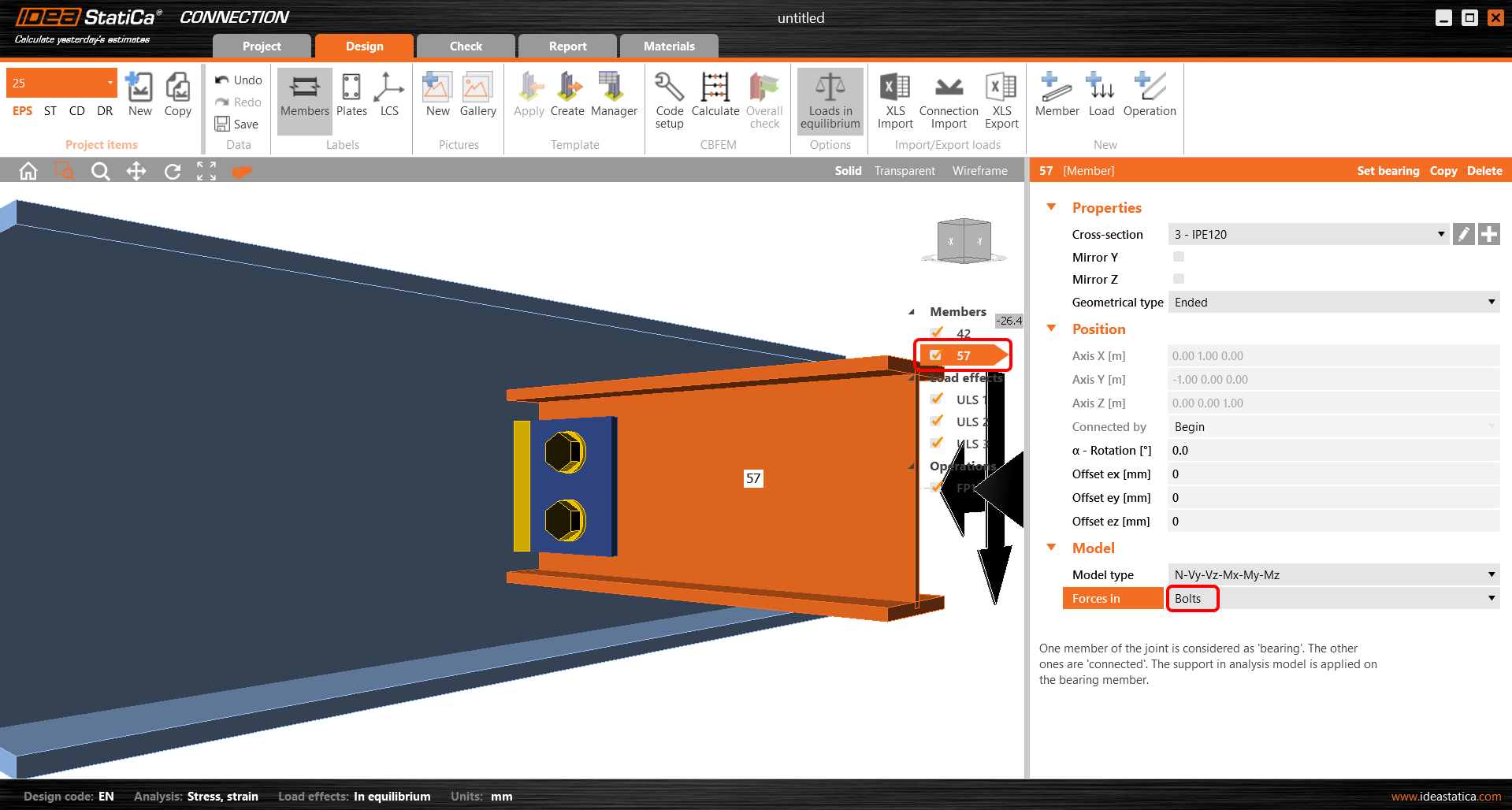
All the processes of using the templates and assigning the position of the shear force in the Bolts will be used for joints 25,27,28.
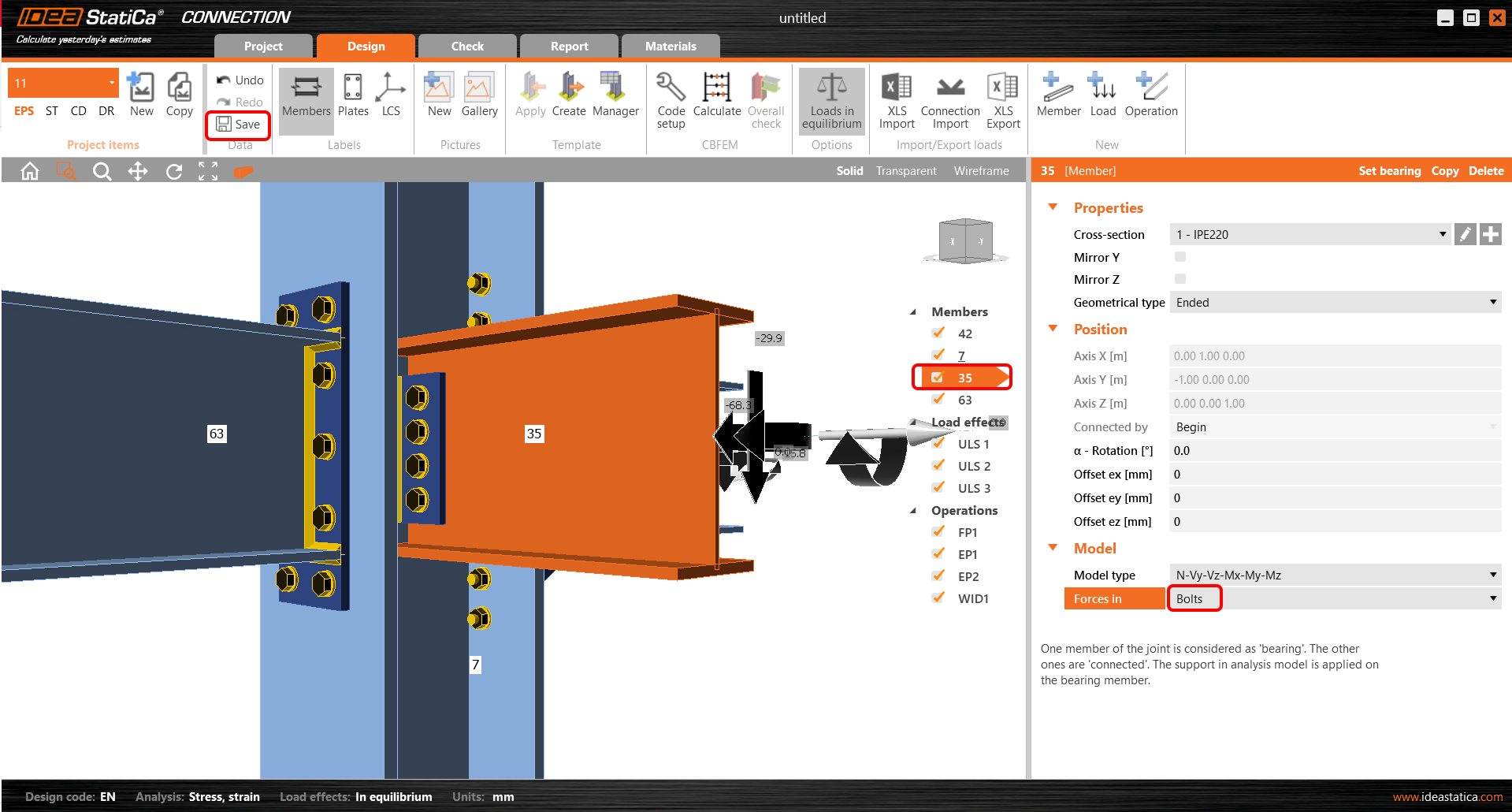
In the joint 11 will be used the same procedure of importing and assigning the template as for joint 2. The position of the forces for member 35 is set to Bolts. As the final step Save and Close the project.
For all joints launch, the bulk analysis use the Calculate all item. You obtain pass/fail code-check for all joints. After that, you push the Finish button to upload all combinations to the Member application.
Open the application Member.
The application has the layout approximately identical similar to the Connection app. In the ribbon start with the Design tab where you set boundary conditions. To all related members are assigned the hinges where all three degrees of freedom (X, Y, Z) are set as a default. The settings of the boundary conditions ought to respect the FEM in SAP2000. For Member 1 restrain the rotation Ry at the beginning and release the translation X, Z at the end of the member.
Perform the steps for member 7 in the same way.
Due to the global model is the member 63 suspended by an inclined tensile member. Set the support only in the Z direction.
4 Check
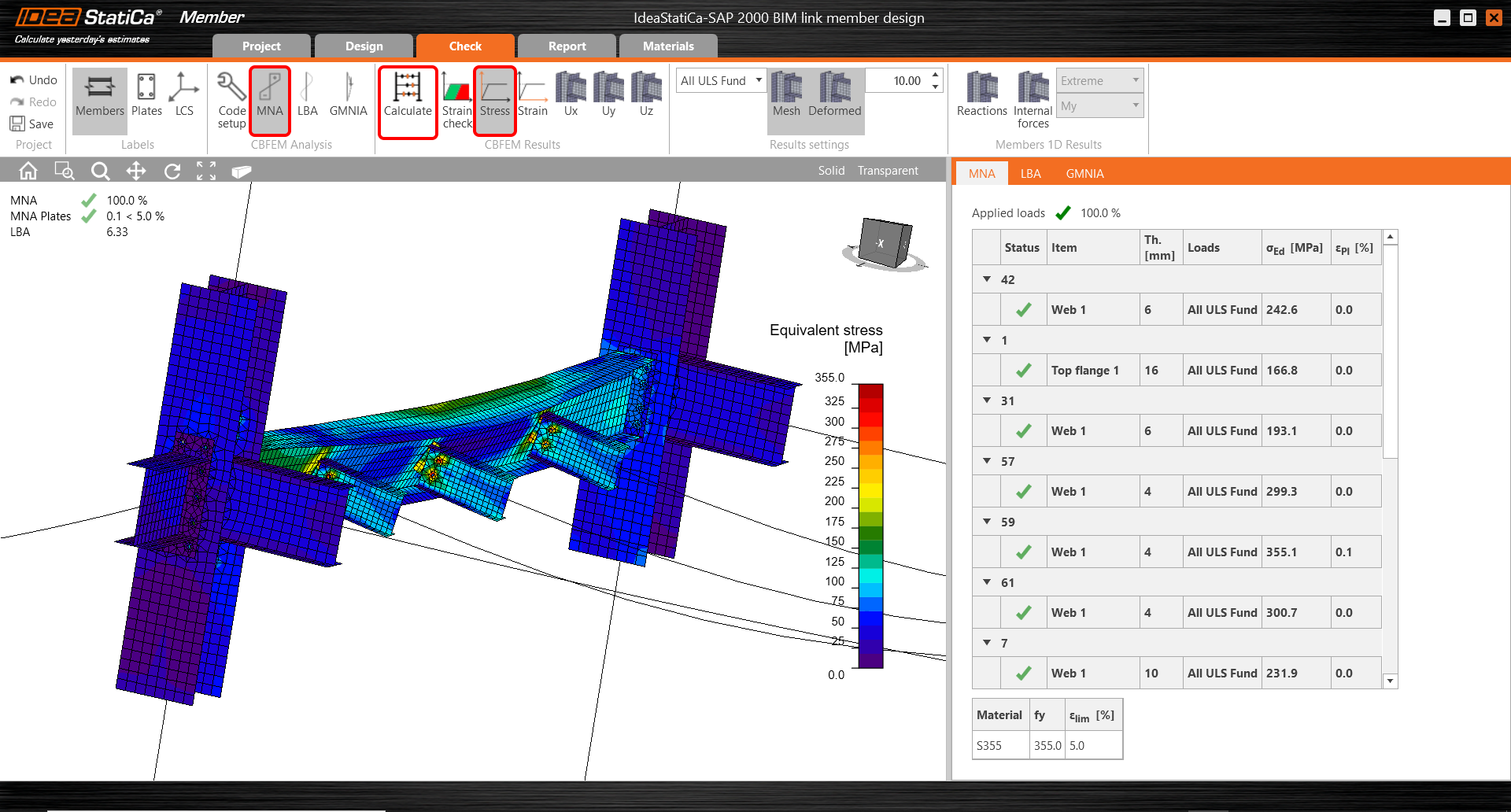
Move to the Check tab and Run MNA (Materially Nonlinear Analysis). After finishing the analysis display the Equivavalent stress on the members.
Move to LBA (Linear buckling analysis) and Run the analysis. You receive the eigenmodes with the critical factors for each of them. These factors are sorted out gradually and the most significant is mainly the first one. The fifth causes the lateral-torsional buckling of the beam.
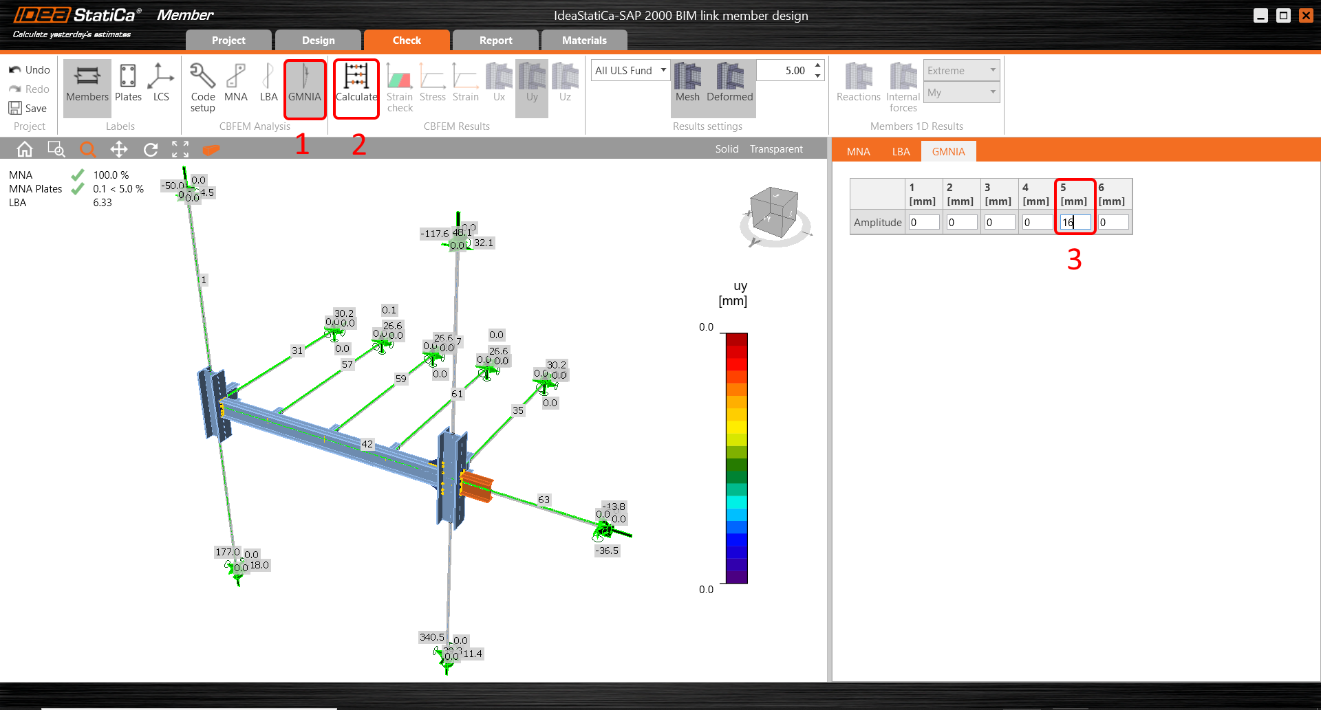
Move to GMNIA and set the imperfection values into the fifth mode. The value of 16 mm is calculated according to the code as described in the article Imperfections. Run the GMNIA.
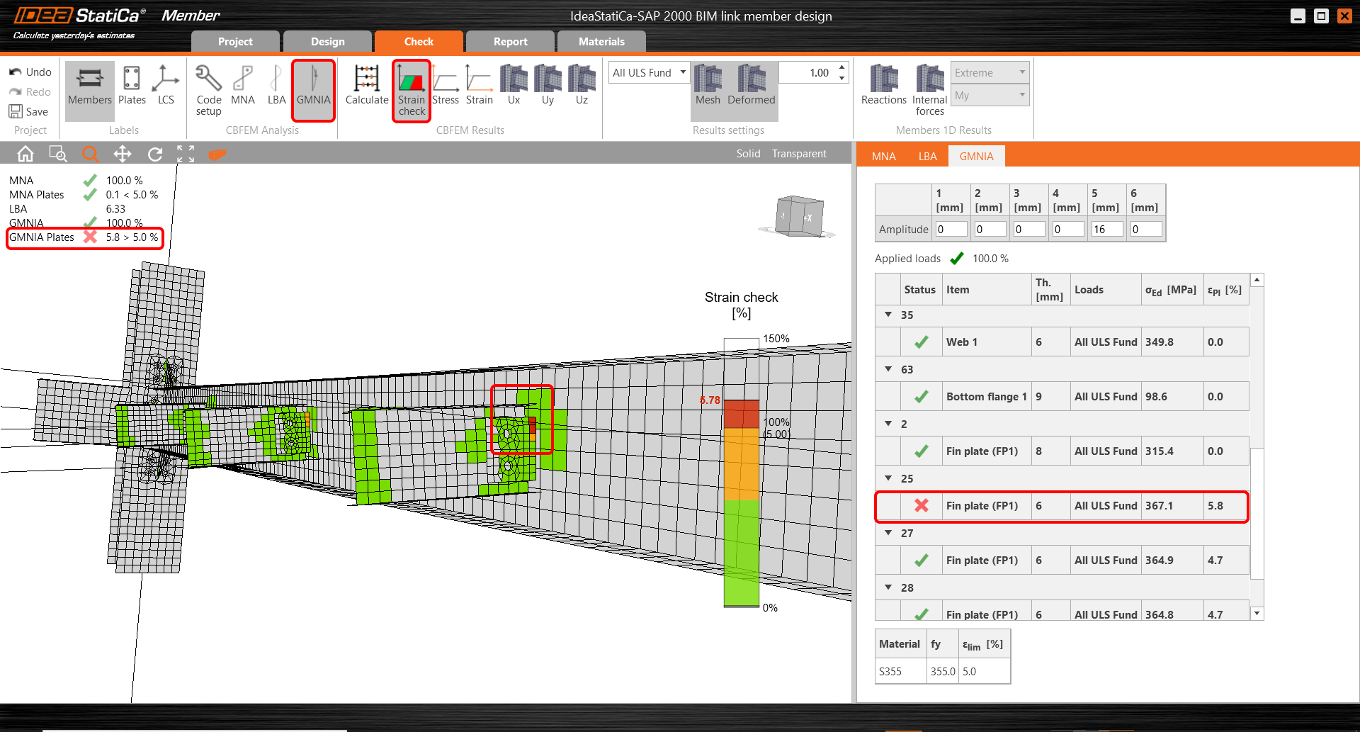
Display the results of the GMNIA and turn on the Strain check. The rate of the plastification is higher than the limit. You can see the differences between MNA and GMNIA from the point of view of the strains.
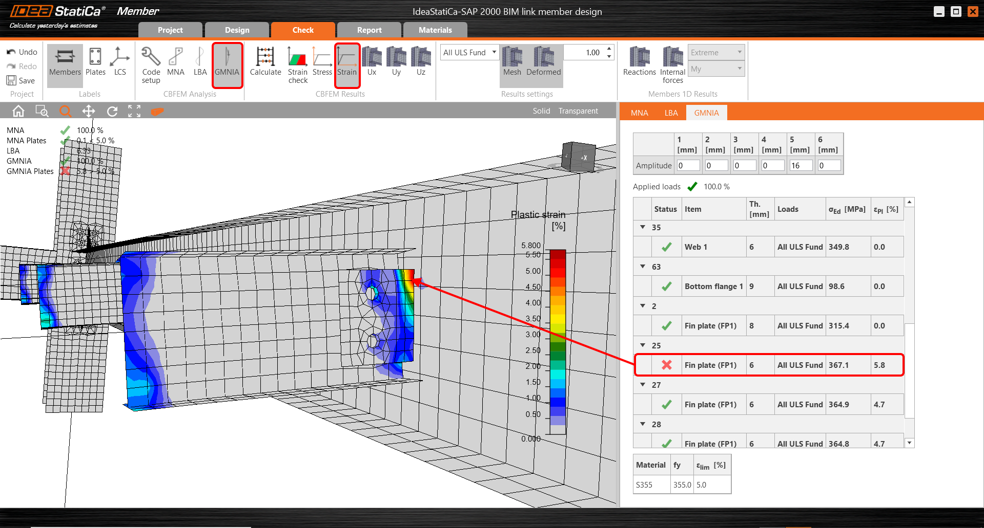
Turn on Strain in the ribbon and Zoom in closer to fin plate where are visible the places of the plastification.
5 Report
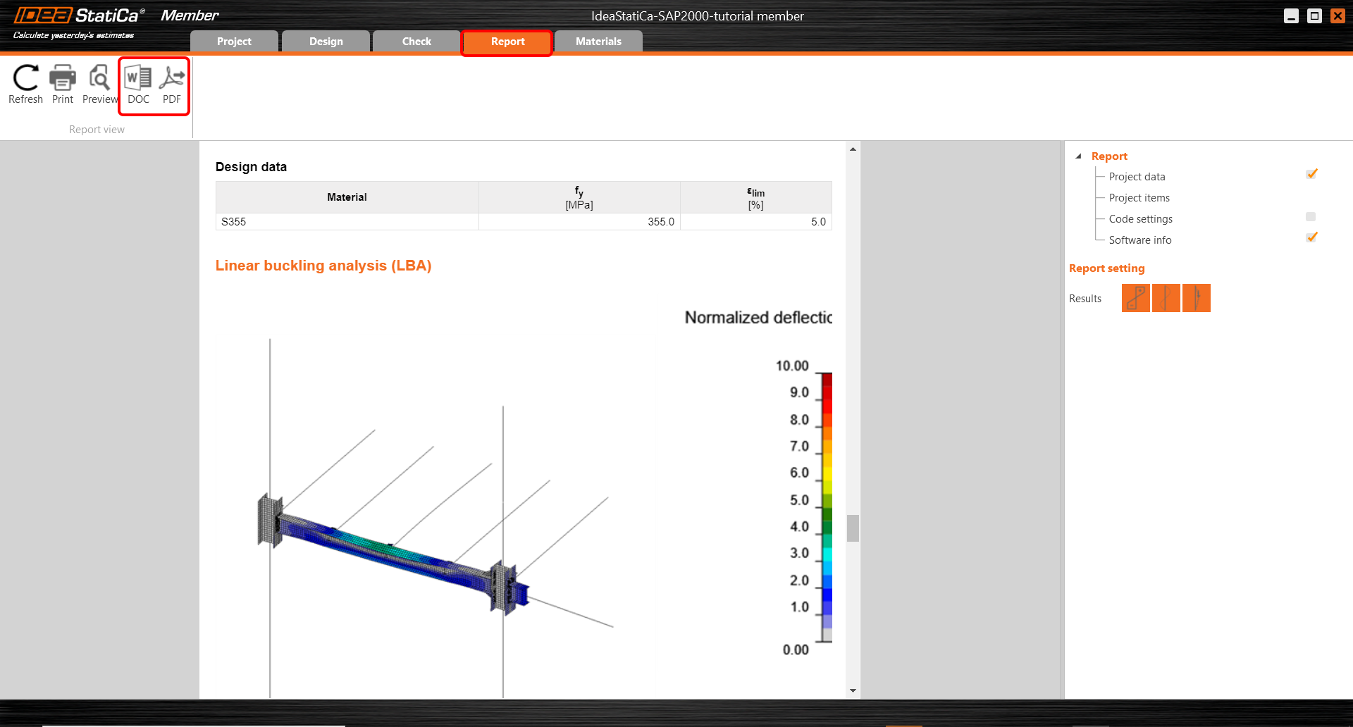
At last, go to the tab Report. IDEA StatiCa offers a fully customizable report to print out or save in an editable format.
Now you have designed, analyzed and code - checked the critical member in the application Member.
6 Synchronize models
Synchronization for Member applications is identical to the same process for SAP2000 BIM link with IDEA StatiCa Connection.
Přiložené soubory ke stažení
- SAP 2000 BIM link member design.zip (ZIP, 73,3 MB)


