Member – Column buckling
Geometry description
Our column HEA 300 is 6 m long and fixed at the bottom by a thick base plate and four anchor bolts with diameter M30. The beam IPE 500 is seated at the column top and loaded at member axis by uniformly distributed load 200 kN/m. The beam overall length is 8 m, and the seat is positioned at the middle. All steel is grade S355.
The column base is assumed to be rigid around both axes and the seated connection at column top as pinned connection around both axes by inspection and experience. Bolts and welds are designed not to fail, which may be verified in IDEA StatiCa Connection.
The ends of the beam are assumed to be restrained against rotation around longitudinal axis and movements in all three directions.
Design
The critical forces for column buckling may be calculated by following equations:
- Flexural buckling around major axis: \(N_{cr,y}=\frac{\pi^2EI_y}{L_{cr,y}^2}\)
- Flexural buckling around minor axis: \(N_{cr,z}=\frac{\pi^2EI_z}{L_{cr,z}^2}\)
- Torsional buckling: \(N_{cr,T}=\frac{1}{i_0^2} \left ( GI_t+ \frac{\pi^2EI_w}{L_{cr,T}^2}\right ) \)
The essential step is the correct assumption of buckling lengths – \(L_{cr,y}, \, L_{cr,z}, \, L_{cr,T}\). The column is fixed at the bottom and pinned at the end, so we assume this buckling shape for both major and minor axis buckling:
The critical buckling forces are calculated as follows:
- \(N_{cr,y} = 21502\,\textrm{kN}\)
- \(N_{cr,z} = 7414\,\textrm{kN}\)
- \(N_{cr,T} = 9661\,\textrm{kN}\)
The column should buckle around minor axis and the buckling resistance should be \(N_{b,Rd} =2818\, \textrm{kN}\).
Are these assumptions correct? Let’s check out in IDEA StatiCa Member.
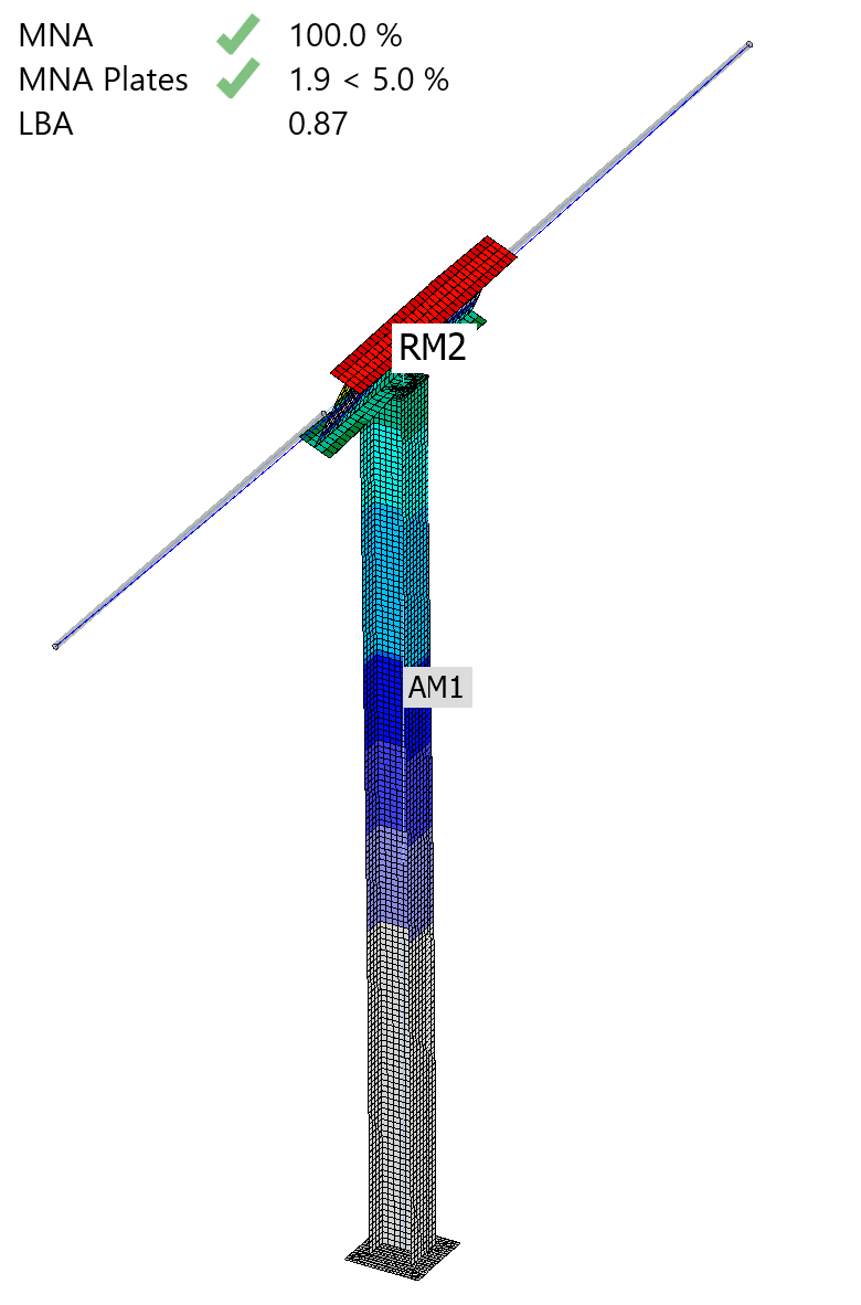
The results are very different. The column buckles around major axis with critical buckling factor of 0.87. That essentially means the column will fail. The buckling resistance of column flexural buckling cannot be higher than the critical buckling force. It is not even necessary to follow with GMNIA.
What is happening? The beam is weak in torsion and also it’s web is weak in bending. The assumptions are clearly wrong. The column deflects and the beam fails by lateral-torsional buckling.
The buckling shape of the column around stronger axis actually looks more like this, which corresponds to buckling length 2*L=12 m.
What can we do? Let’s modify the connection. Adding a stiffener may perhaps be all that is needed.
The stiffener helps greatly, instead of buckling factor 0.87, we now see 5.13 for the 1st buckling mode shape. The shape now also looks very different. Although the flexural buckling around the stronger axis still looks like we should use rather buckling length \(2L\) in our hand calculations, the beam no longer tips off the column seat. Using conservatively \(2L\) as a buckling length results in \(N_{cr,y} = 2634 \, \textrm{kN}\). Comparison to Member result of \(5.13 \cdot 800 = 4104 \, \textrm{kN}\) shows that the beam is now stabilizing the column.
Buckling factor over 5 already looks promising. But it is above 15 (EN 1993-1-1, Cl. 5.2.1 (3)) and buckling check must be provided. Let’s apply initial imperfections and run GMNIA. Table 6.2 in EN 1993-1-1 suggests buckling curve b for buckling around major axis. In Table 5.1 we can then read \(e_0/L = 1/250\). That results in 24 mm for the first buckling mode shape. Let’s also add local imperfections for the second mode shape with a close factor of 7.54. The amplitude according to EN 1993-1-5 should be b/200 where b is the width of the buckling panel. Amplitude 1.31 mm was added. The flowchart for combining global and local imperfections for open sections is provided here.
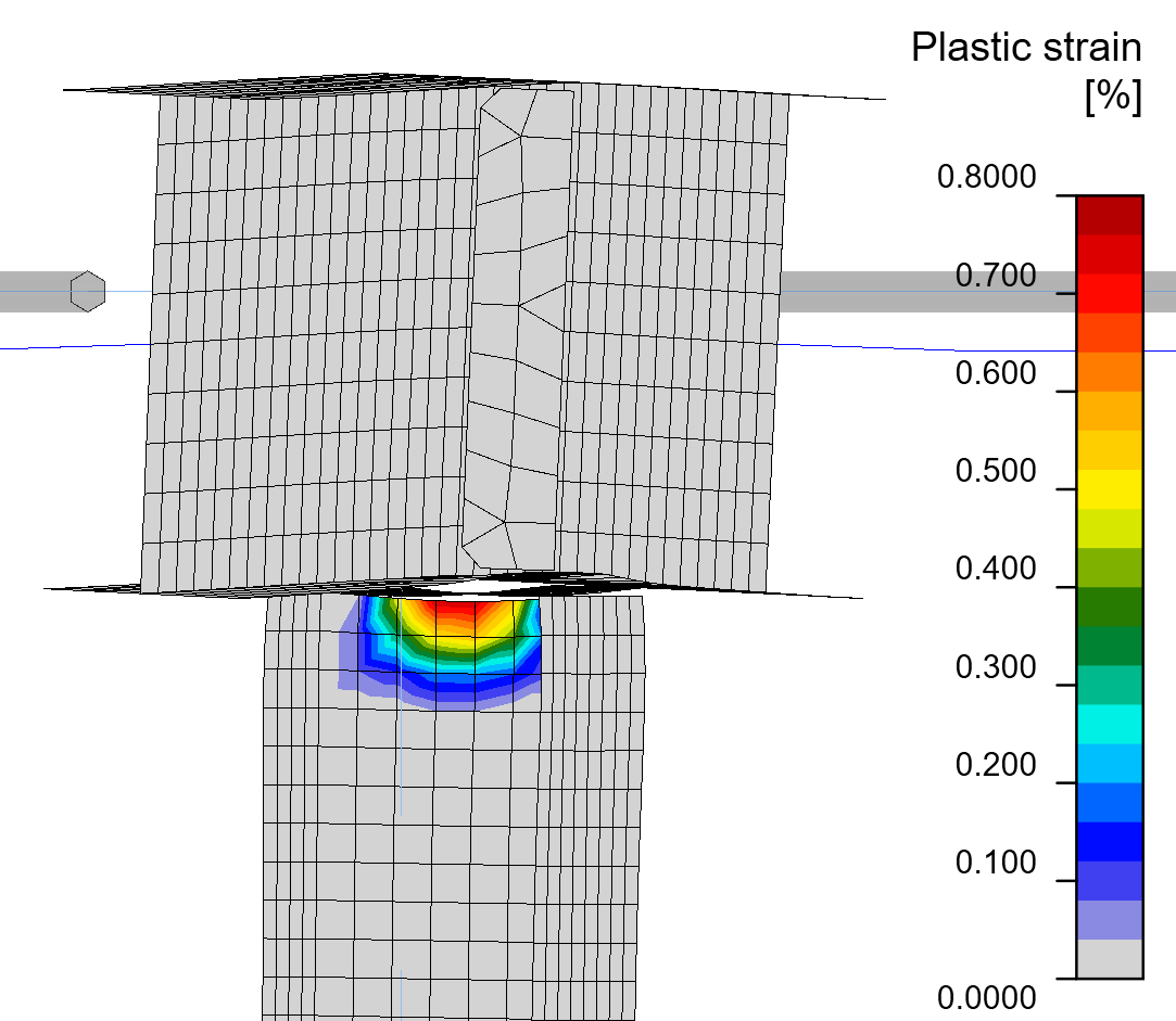
The GMNIA shows that the column and beam remain standing, although the column is already leaning to the side.
The highest plastic strain is at the column web but it does not exceed 5% plastic strain limit.
Final thoughts
The article shows the importance of connection detailing and how profoundly it may affect member design. How do you divide jobs in your company? Do you use delegated design for connections? How do you estimate buckling lengths of members?
As a connection designer, what information do you have available about member design? Do you always add a stiffener in a seated connection?
Acknowledgments
The topic was inspired by discussions at Dutch Technical Committee 10 for steel connection design and a presentation by Larry Muir at NASCC conference 2023.


