Subcode: LRFD
Type of connection: Anchorage
Unit system: Metric
Designed acc. to: ACI 318-14
Investigated: Anchors in tension and shear close to an edge
Plate material: A709, Gr. 50
Bolts: M12 A325M
Concrete grade: 4000 psi
Geometry
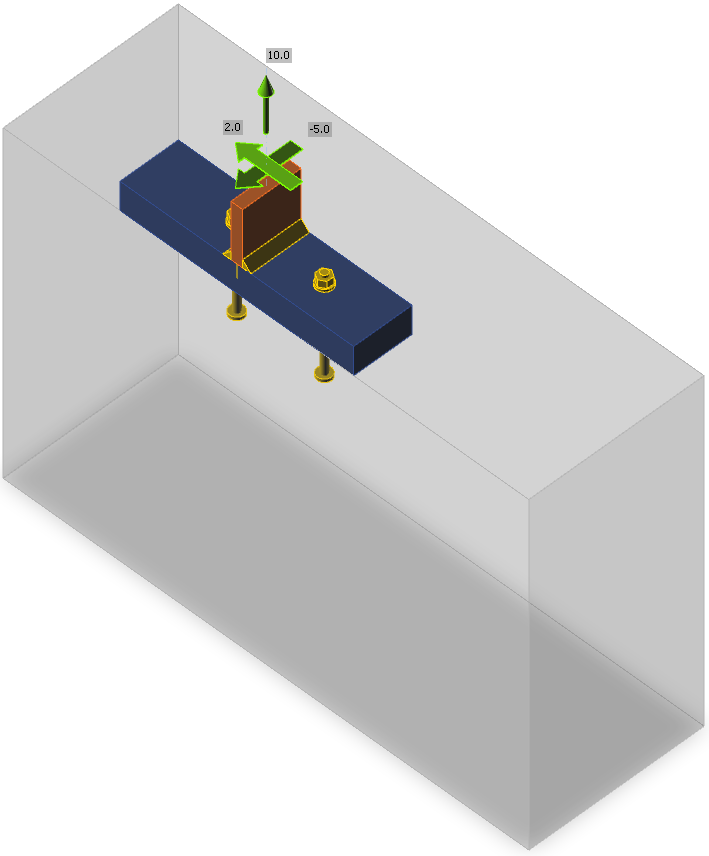
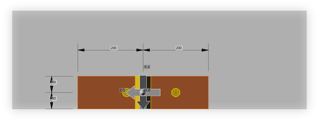
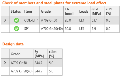
The anchor layout and base plate–column T-section is unrealistic but it serves as a verification of most features in anchor design. The offset of concrete block to the base plate is 200 mm upwards and to the left, 300 mm to the right and 0 mm downwards. The height of concrete block is 600 mm. Left and right anchors are 50 mm and 100 mm from the center of the column, respectively. This serves to achieve tensile and shear load eccentricity. All plates are designed to stay in elastic state.
Applied load
The column is loaded by tensile force 10 kN and shear forces in y and z direction, –5 kN and 2 kN. Both tensile and shear forces are acting on an eccentricity due to the position of the anchors.
Procedure
The anchors are designed according to ACI 318-14 – Chapter 17. Cracked plain concrete is assumed in the design. All loads are considered as static. Anchors are M12 A325M, cast-in headed with circular washer plates with the diameter of 24 mm. Shear forces are transferred via anchors. The strength of plates and welds is sufficient and is not checked here.
Note: The conversion of imperial units to metric units of nonhomogenous formulas is in Appendix B of ACI 318-14. The formulas give similar but not exactly the same results. To avoid different utilization for imperial and metric units, the imperial units are preferred and the coefficients in nonhomogenous formulas are slightly modified for metric units, e.g. in Equation 17.4.4.1, instead of coefficient 13, the more precise coefficient 13.2855 is used.
Manual calculation
The check of anchors is provided according to ACI 318-14 – Chapter 17. Steel strength in tension and shear and pullout strength is provided for individual anchors and concrete breakout strength in tension and shear, concrete side-face blowout strength, and concrete pryout strength is provided for group of anchors. It is assumed concrete is plain and in cracked condition.
Force distribution
The tensile force is transferred via 2 anchors, one is 50 mm from force vector origin, the other is 100 mm. It is presumed that the closer anchor transfers 2/3 of the tensile force and the farther 1/3, i.e. the closer anchor is loaded by tensile force Nf1 = 6.67 kN, the farther by Nf2 = 3.33 kN. The force eccentricity of the group of anchors is 25 mm.
The shear force in the direction to the closest edge is transferred via 2 anchors, one is 50 mm from force vector origin, the other is 100 mm. It is presumed that the closer anchor transfers 2/3 of the shear force and the farther 1/3, i.e. the closer anchor is loaded by shear force Vfx1 = 3.33 kN, the farther by Vfx2 = 1.67 kN. The force eccentricity of the group of anchors is 25 mm. The shear force in the direction parallel to the closest edge, 2 kN, is distributed equally between both anchors. The vector sums of shear forces are Vf1 = 3.48 kN, Vf2 = 1.94 kN, and for a group of anchors Vf = 5.39 kN.
Steel strength of anchor in tension
Steel strength of anchor in tension is determined according to ACI 318-14 – 17.4.1 as
ϕNsa = ϕ Ase,Nfuta = 0.7 ⋅ 84 ⋅ 827.4 = 48.7 kN ≥ Nf1 = 6.67 kN
where:
- ϕ = 0.7 – strength reduction factor for anchors in tension according to ACI 318-14 – 17.3.3
- Ase,N = 84 mm2 – tensile stress area
- futa = 827.4 MPa – specified tensile strength of anchor steel and shall not be greater than 1.9 fya and 120 ksi
Utilization: Nf1 / ϕNsa = 6.67 / 48.7 = 13.7 %
Concrete breakout strength in tension
Concrete breakout strength is designed according to the Concrete Capacity Design (CCD) in ACI 318-14 – Chapter 17.4.2. The anchors are treated as a group because they are close to each other, the spacing s = 150 mm ≤ 3 ⋅ hef = 3 ⋅ 100 = 300 mm.
\[ \phi N_{cbg} = \phi \frac{A_{Nc}}{A_{Nco}} \psi_{ec,N} \psi_{ed,N} \psi_{c,N} \psi_{cp,N} N_b \]
where:
- ϕ = 0.7 – strength reduction factor for anchors in tension according to ACI 318-14 – 17.3.3
- ANc = (50 + 150 + 12) ⋅ (150 + 12 + 150 + 12 + 150) = 100 488 mm2 – actual concrete breakout cone area for a group of anchors that create common concrete cone. According to Cl. 17.4.2.8, the projected area of the failure surface by projecting the failure surface outward from the effective perimeter of the washer plate.
- ANco = 9 hef2 = 9 ⋅ 1002 = 90 000 mm2 – concrete breakout cone area for single anchor not influenced by edges
- \( \psi_{ec,N} = \frac{1}{1+\frac{2 e'_N}{3 h_{ef}}} = \frac{1}{1+\frac{2 \cdot 25}{3 \cdot 100}}=0.857 \) – modification factor for anchor groups loaded eccentrically in tension
- \( \psi_{ed,N} = \min \left ( 0.7 + \frac{0.3 c_{a,min}}{1.5 h_{ef}}, 1 \right ) = \min \left ( 0.7 + \frac{0.3 \cdot 50}{1.5 \cdot 100}, 1 \right ) = 0.8 \) – modification factor for edge distance
- ca,min = 50 mm– smallest distance from the anchor to the edge
- Ψc,N = 1 – modification factor for concrete conditions
- Ψcp,N = 1 for cast-in anchor
- \( N_b = k_c \lambda_a \sqrt{f'_c} h_{ef}^{1.5} = 10 \cdot 1 \cdot \sqrt{27.6} \cdot 100^{1.5} = 52.7 \,\textrm{kN} \)– basic concrete breakout strength of a single anchor in tension in cracked concrete; hef ≤ 280 mm (11 in)
- kc = 10 for cast-in anchors and metric units
- hef = 100 mm – depth of embedment; according to Chapter 17.4.2.3 in ACI 318-14, the effective embedment depth hef is reduced to \( h_{ef} = \max \left ( \frac{c_{a,max}}{1.5}, \frac{s}{3} \right ) \)
- if anchors are located less than 1.5 hef from three or more edges
- s = 150 mm – spacing between anchors
- ca,max = 350 mm – maximum distance from an anchor to one of the three close edges
- λa = 1 – modification factor for lightweight concrete
- f'c = 27.6 MPa – concrete compressive strength
\[ \phi N_{cbg} = 0.7 \cdot \frac{100488}{90000} \cdot 0.857 \cdot 0.8 \cdot 1 \cdot 1 \cdot 52.7 = 28.3 \,\textrm{kN} \ge N_f = 10\,\textrm{kN} \]
Utilization: Nf / ϕNcbg = 10 / 28.3 = 35.4 %
Pullout strength in tension
Concrete pullout strength of an anchor is defined in ACI 318-14 – 17.4.3 as
ϕNpn = ϕΨc,PNp = 0.7 ⋅ 1 ⋅ 74.9 = 52.4 kN ≥ Nf1 = 6.67 kN
where:
- ϕ = 0.7 – strength reduction factor for anchors in tension according to ACI 318-14 – 17.3.3
- Ψc,P = 1 – modification factor for concrete condition, Ψc,P = 1.0 for cracked concrete
- NP = 8 Abrgf'c = 8 ⋅ 339.3 ⋅ 27.6 = 74.9 kN – for headed anchor – Cl. 17.4.3.4
- Abrg = π ⋅ (dwp2 – da2) / 4 = π ⋅ (242 – 122) / 4 = 339.3 mm2– bearing area of the head of anchor bolt
- f'c = 27.6 MPa – concrete compressive strength
Utilization: Nf1 / ϕNpn = 6.67 / 52.4 = 12.7 %
Concrete side-face blowout strength
Concrete side-face blowout strength of headed anchor in tension is defined in ACI 318-14 – 17.4.4 as
\[ \phi N_{sb} = \phi 13 c_{a1} \sqrt{A_{brg}} \sqrt{f'_c} \]
The concrete side-face blowout strength is multiplied by reduction factor for multiple headed anchors close to an edge and close to each other according to Cl. 17.4.4.2:
\[ 1+\frac{s}{6 c_{a1}} = 1+\frac{150}{6 \cdot 50} = 1.5 \le 2 \]
where:
- ϕ = 0.7 – strength reduction factor for anchors in tension according to ACI 318-14 – 17.3.3
- ca1 = 50 mm – shorter distance from the centreline of an anchor to an edge
- ca2 = 350 mm – longer distance, perpendicular to ca1, from the centreline of an anchor to an edge
- Abrg = 339.3 mm2 – bearing area of the head of anchor bolt
- f'c = 27.6 MPa – concrete compressive strength
- hef = 100 mm – depth of embedment
- s = 150 mm – spacing between anchors
\[ \phi N_{sbg} = 1.5 \cdot \phi 13 c_{a1} \sqrt{A_{brg}} \sqrt{f'_c} = 1.5 \cdot 0.7 \cdot 13 \cdot 50 \cdot \sqrt{339.3} \cdot \sqrt{27.6} = 67.4\,\textrm{kN} \ge N_{f} = 10\,\textrm{kN} \]
Utilization: Nf / ϕNcbg = 10 / 67.4 = 26.7 %
Steel strength in shear
The steel strength in shear is determined according to ACI 318-14 – 17.5.1 as
ϕVsa = ϕ 0.6 Ase,Vfuta = 0.65 ⋅ 0.6 ⋅ 84 ⋅ 827.4 = 27.1 kN ≥ Vf1 = 3.48 kN
where:
- ϕ = 0.65 – strength reduction factor for anchors in tension according to ACI 318-14 – 17.3.3
- Ase,V = 84 mm2 – tensile stress area
- futa = 827.4 MPa – specified tensile strength of anchor steel and shall not be greater than 1.9 fya and 120 ksi
Utilization: Vf1 / ϕVsa = 3.48 / 27.1 = 12.7 %
Concrete breakout strength in shear
Concrete breakout strength of an anchor group in shear is designed according to ACI 318 14 – 17.5.2.
\[ \phi V_{cbg} = \phi \frac{A_V}{A_{Vo}} \psi_{ec,V} \psi_{ed,V} \psi_{c,V} \psi_{h,V} \psi_{\alpha,V} V_b \]
where:
- ϕ = 0.65 – strength reduction factor for anchors in shear according to ACI 318-14 – 17.3.3
- Av = (50 ⋅ 1.5) ⋅ (50 ⋅ 1.5 + 150 + 50 ⋅ 1.5) = 22 500 mm2 – projected concrete failure area of an anchor or group of anchors
- Avo = 4.5 ca12 = 4.5 ⋅ 502 = 11 250 mm2 – projected concrete failure area of one anchor when not limited by corner influences, spacing or member thickness
- \( \psi_{ec,V} = \frac{1}{1+\frac{2 e'_V}{3 c_{a1}}}= \frac{1}{1+\frac{2 \cdot 25}{3 \cdot 50}}=0.75 \) – modification factor for anchor groups loaded eccentrically in shear
- \( \psi_{ed,V} = 0.7 + 0.3 \frac{c_{a2}}{1.5 c_{a1}} = 0.7 + 0.3 \frac{350}{1.5 \cdot 50} = 2.1\le 1.0 \) – modification factor for edge effect
- Ψc,V = 1 – modification factor for concrete condition; Ψc,V = 1.0 for cracked concrete
- \( $\psi_{h,V} = \sqrt{\frac{1.5 c_{a1}}{h_a}} = \sqrt{\frac{1.5 \cdot 50}{600}} = 0.354 \ge 1 \)– modification factor for anchors located in a concrete member where ha < 1.5 ca1
- \( \psi_{\alpha ,V} = \sqrt{\frac{1}{(\cos \alpha_V )^2 + (0.5 \sin \alpha_V)^2}}=\sqrt{\frac{1}{(\cos 21.8^\circ )^2 + (0.5 \sin 21.8^\circ)^2}} = 1.056 \)– modification factor for anchors loaded at an angle 90° − αV with the concrete edge; in ACI 318-14 – 17.5.2.1 are only discrete values, equation is taken from FIB bulletin 58 – Design of anchorages in concrete (2011)
- ha = 600 mm – height of a failure surface on the concrete side
\[ V_b = \min \left ( 0.6 \left ( \frac{l_e}{d_a} \right )^{0.2} \lambda_a \sqrt{d_a} \sqrt{f'_c} c_{a1}^{1.5}, 3.7 \lambda_a \sqrt{d_a} \sqrt{f'_c} c_{a1}^{1.5} \right ) \]
\[ V_b = \min \left ( 0.6 \left ( \frac{96}{12} \right )^{0.2} \cdot 1.0 \cdot \sqrt{12} \cdot \sqrt{27.6} \cdot 50^{1.5} = 5.666 \, \textrm{kN}, 3.7 \cdot 1.0 \cdot \sqrt{12} \cdot \sqrt{27.6} \cdot 50^{1.5} = 6.993 \, \textrm{kN} \right ) = 5.666 \, \textrm{kN} \]
- le = hef = 100 mm ≤ 8 da = 8 ⋅ 12 = 96 mm – load-bearing length of the anchor in shear
- da = 12 mm – anchor diameter
- f'c = 27.6 MPa – concrete compressive strength
- ca1 = 50 mm – edge distance in the direction of load, ca2 ≥ 1.5 ca1 and ha ≥ 1.5 ca1
- ca2 = 350 mm – edge distance in the direction perpendicular to load
\[ \phi V_{cbg} = 0.65 \cdot \frac{22500}{11250} \cdot 0.75 \cdot 1.0 \cdot 1.0 \cdot 1.0 \cdot 1.056 \cdot 5.666 = 5.835 \, \textrm{kN} \ge V_f = 5.39 \, \textrm{kN} \]
Utilization: Vf / ϕVcbg = 5.39 / 5.835 = 92.3 %
Concrete pryout strength of anchor in shear
Concrete pryout strength is designed according to ACI 318-14 – 17.5.3. It is assumed that all anchors are in tension and no eccentricity is present for concrete breakout strength.
ϕVcp = ϕkcpNcp = 0.65 ⋅ 2 ⋅ 47.1 = 61.2 kN ≥ Vf = 5.39 kN
where:
- ϕ = 0.65 – strength reduction factor for anchors in shear according to ACI 318-14 – 17.3.3
- kcp = 2.0 for hef ≥ 50 mm
- Ncp = Ncb = 47.1 kN (concrete breakout strength – all anchors are assumed in tension) in case of cast-in anchors
Utilization: Vf / ϕVcp = 5.39 / 61.2 = 5.7 %
Interaction of tensile and shear forces
Interaction of tensile and shear forces is assessed according to ACI 318-14 – R17.6.
\[ \left ( \frac{N_{ua}}{N_n} \right )^{\zeta} + \left ( \frac{V_{ua}}{V_n} \right )^{\zeta} = \left ( 0.354 \right )^{5/3} + \left ( 0.923 \right )^{5/3}= 1.062 \le 1.0 \]
where:
- Nua and Vua – design forces acting on an anchor
- Nn and Vn – the lowest design strengths determined from all appropriate failure modes
- ς = 5 / 3
The strength of anchorage is not sufficient to transfer combined tensile and shear forces.
Check in IDEA StatiCa Connection
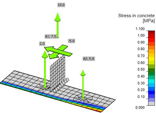
In addition, the results of welds and concrete block in compression are shown. Loading of these components is negligible and therefore also utilization.
Comparison
The force distribution in IDEA StatiCa Connection is slightly different than in manual assessment. The column and base plate are deformed and the base plate is in contact with concrete block. The bearing stress increases the forces in anchors. Thus, factors taking into account force eccentricity are slightly different. Concrete side-face blowout strength is in IDEA StatiCa Connection checked for each anchor separately but in manual calculation, it can be checked as a group to achieve slightly higher resistance. Due to these reasons, some individual load resistances are slightly different but only by a few percents. The final utilization – interaction of tensile and shear forces – is nearly identical, 106.2 % in manual assessment and 107.7 % in IDEA StatiCa.


