Educational center in Tallinn
About the project
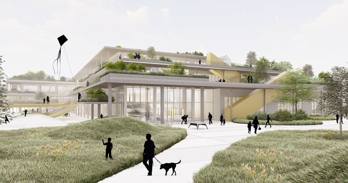
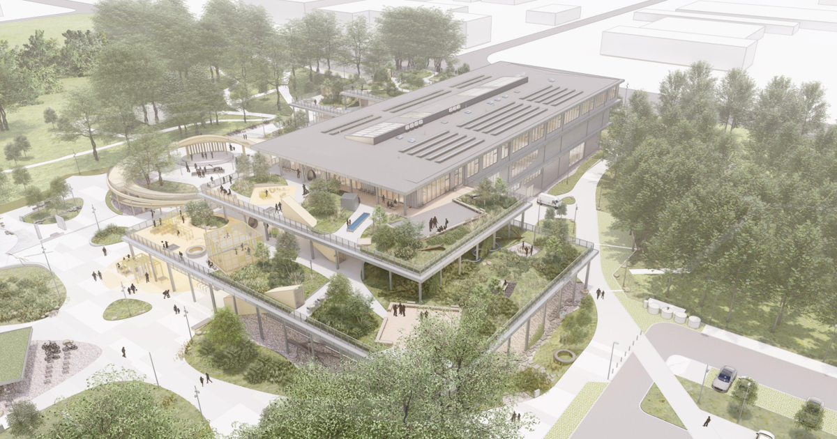
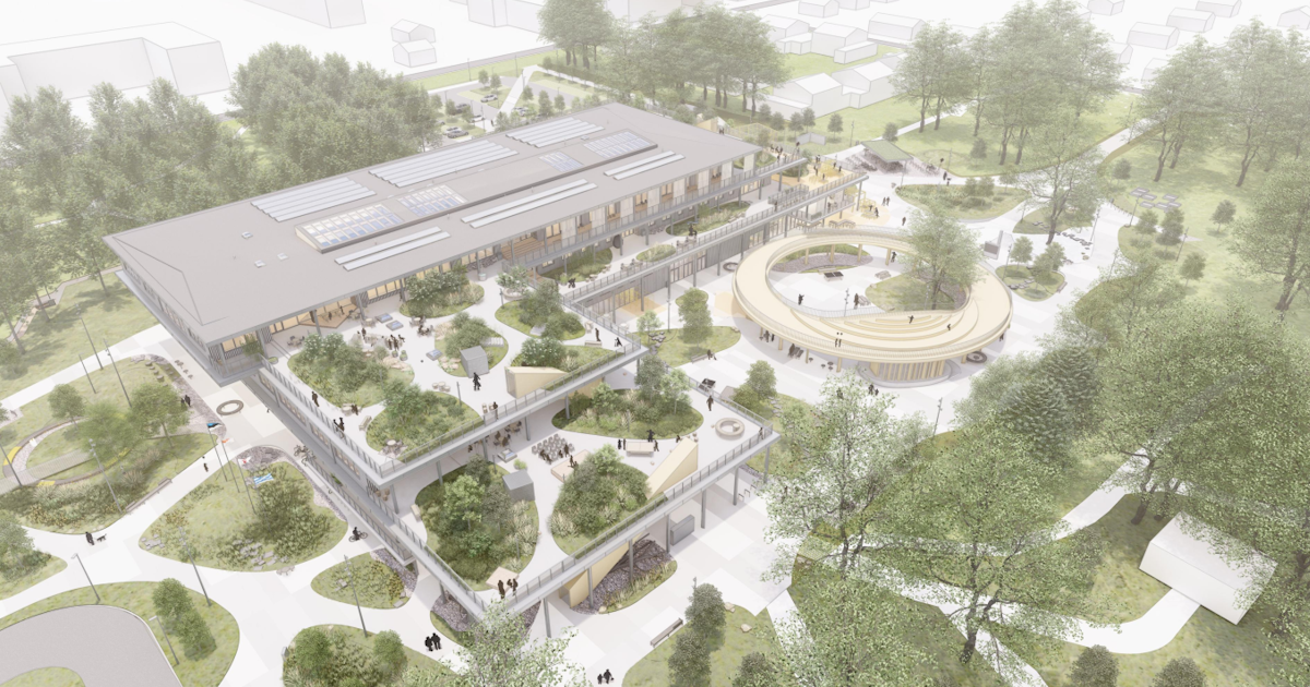
The educational center in Tallinn is a four-story structure designed to replace an outdated facility with a modern, multifunctional building. Spanning a gross area of 13,566 m², the building stands 18 meters tall and incorporates a combination of concrete, steel, and masonry as its primary materials. The vertical load-bearing system is predominantly composed of concrete columns and masonry walls, which not only provide the necessary support but also contribute to the building's global stiffness. Horizontal load-bearing elements consist primarily of hollow core slabs supported by precast beams, with certain sections utilizing cast-in-place flat slabs for additional structural support.
The fourth floor and roof structure showcase a shift towards steel construction, using steel columns and beams for enhanced flexibility and reduced weight. The building is supported by 831 piles with a total length of 21,000 meters, ensuring a solid foundation despite challenging soil conditions. The total concrete volume used in the structure, excluding piles, amounts to 3,560 m³, and the steel components weigh approximately 430,000 kg.
\[ \textsf{\textit{\footnotesize{Architectural visualization of the Educational center}}}\]
Engineering challenges
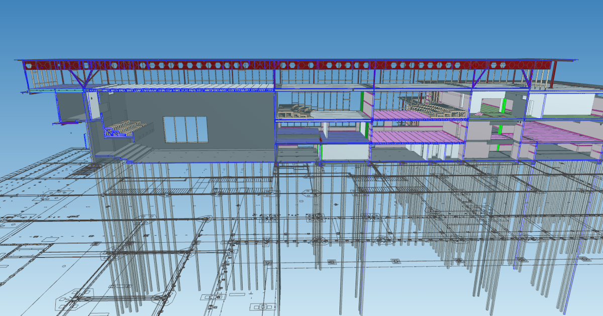
One of the primary challenges in this project was the design of an 80.70-meter-long castellated beam. This beam needed to cover extensive spans on the third floor, ensuring an open, column-free space as per the architectural vision. Beyond supporting the structural integrity of the large open spaces, the beam also had to accommodate the passage of a ventilation duct system through its structure.
\[ \textsf{\textit{\footnotesize{Section view on the castellated beam in IFC reader software}}}\]
The engineering complexity was further heightened by the need to support six spans across the entire top floor, with the longest span reaching 27.49 meters. Additionally, the beam's final span was designedesgined as a cantilever, which not only extended outward but also supported a portion of the floor slab below, adding significant load and requiring meticulous structural analysis and design.
After evaluating all the inputs, project engineers Martin Truuts and Karl Kimmel determined that a castellated beam would be the optimal solution. The castellated beam's design naturally provides openings for the duct system to pass through, while its high effective height allows for significant load-bearing capacity with a relatively minimal use of material.
Choosing the castellated beam was clearly the best option but also introduced additional challenges, particularly in ensuring the structure's stability against lateral-torsional buckling and other forms of buckling. As a continuous beam, stabilizing the lower flange in the supported areas was essential. Typically, diagonal restraints would be used to address this issue, but this solution was not feasible due to the placement of ventilation pipes and architectural requirements for the space adjacent to the beam. As a result, "secondary beams", perpendicular to the castellated beam, were utilized to provide the necessary stabilization.
Solutions and results
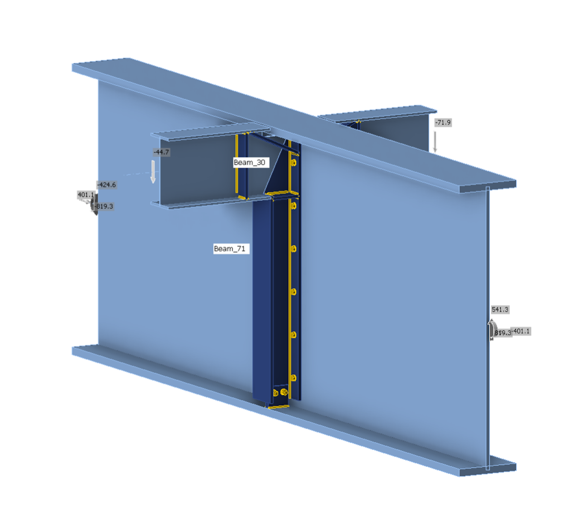
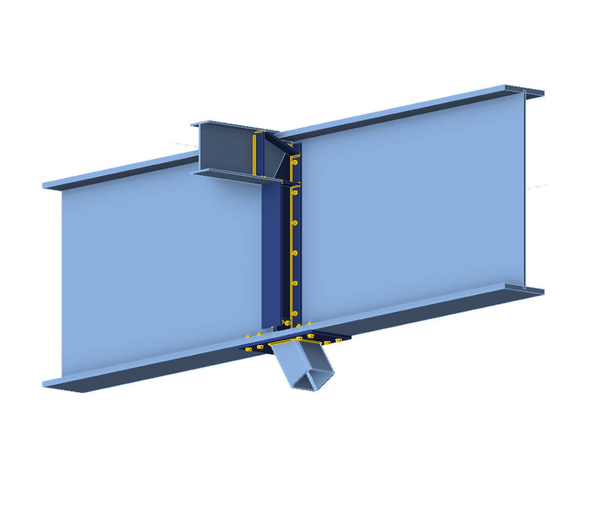
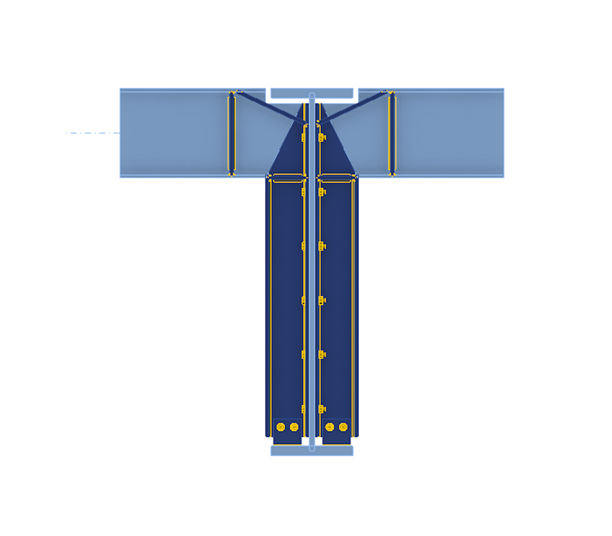
As previously mentioned, stability issues were addressed by connecting "secondary beams" to the sides of the castellated beam. The design leveraged the bending stiffness of the secondary beams, extending this stiffness to the lower flange of the castellated beam through a robust connection design. This approach effectively stabilized the lower flange. In essence, the connection between the secondary and castellated beams was so robust and stiff that it caused the secondary beams in adjacent spans to function as continuous beams, thereby influencing the distributions of loads and internal forces, which in this case also meant transferring more load to the castellated beams.

Estonia
To address the stability issues and incorporate connection stiffness into the design, the engineers integrated IDEA StatiCa's suite of applications—Checkbot, Member, and Connection—into their workflow. Engineers Karl Kimmel and Martin Truuts followed a structured approach:
Global Model Creation: The process began with the creation of a global model in Robot Structural Analysis (RSA) software, where loads and load combinations were introduced.
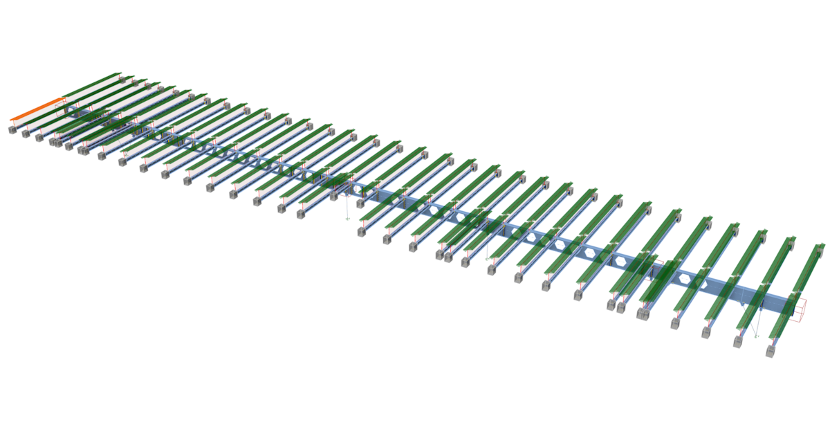
BIM Link Integration: Karl then used the BIM link to import the entire structure, including the internal forces of all load combinations, into IDEA StatiCa Checkbot.
\[ \textsf{\textit{\footnotesize{The model imported into Checkbot with internal forces}}}\]
Connection Design and Stiffness Calculation: In IDEA StatiCa Connection, individual joints were designed, and the stiffness of these connections was calculated. This stiffness was then reintroduced into the RSA model, influencing the bending moment diagram of the castellated beam and the behavior of the related columns.
\[ \textsf{\textit{\footnotesize{Connection designs used in the model in Member application}}}\]
Member Modeling: The model was then recreated from scratch in IDEA StatiCa Member. All beams were modeled as "analyzed members," using shell elements for detailed representation. Connections were modeled and assigned to the appropriate joints, and critical loads were applied to the model for final analysis.
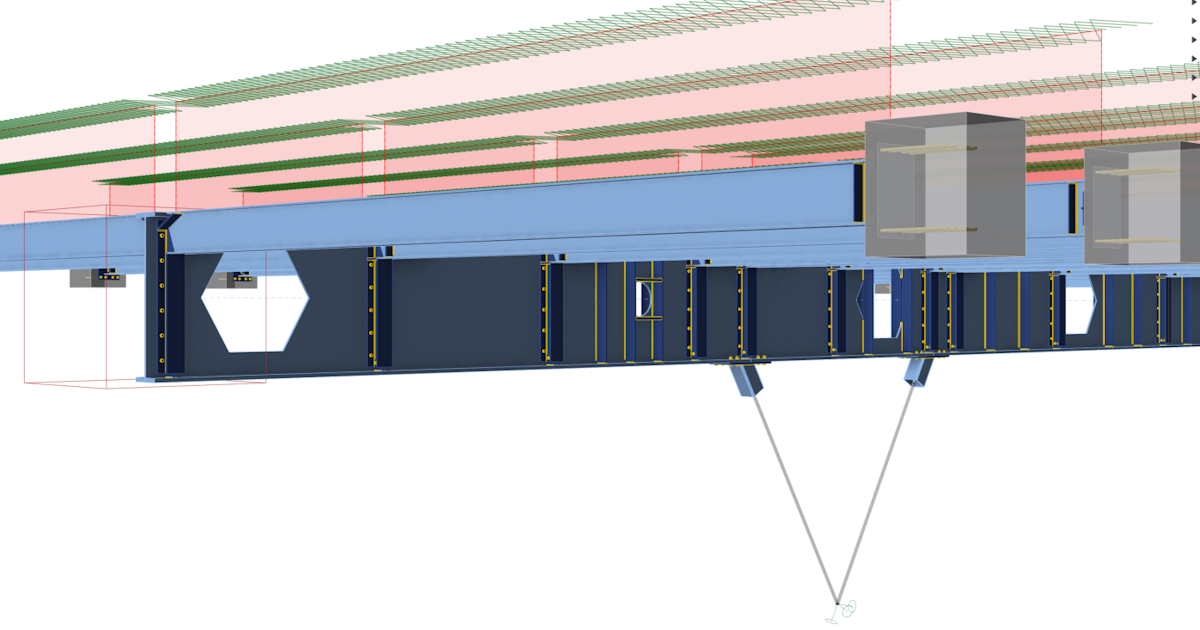
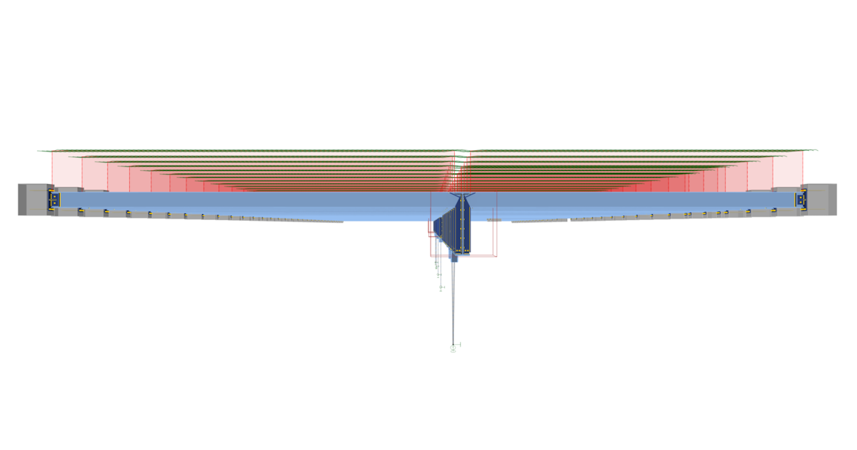
\[ \textsf{\textit{\footnotesize{Various views on the model in Member application}}}\]
Analysis of Members: In IDEA StatiCa Member, buckling shapes and corresponding critical buckling factors were identified through Linear Buckling Analysis. The critical buckling shapes were then assigned initial imperfections and further analyzed using Geometrically and Materially Nonlinear Analysis with Imperfections (GMNIA). This process helped identify weak points in the design, allowing for necessary adjustments. These steps were iterative, with each cycle refining the design to enhance stability and performance.
Karl and Martin analyzed approximately six buckling shapes, focusing primarily on global buckling modes, as there were few local buckling shapes present. They addressed potential local buckling issues in the design by incorporating stiffeners to eliminate them.
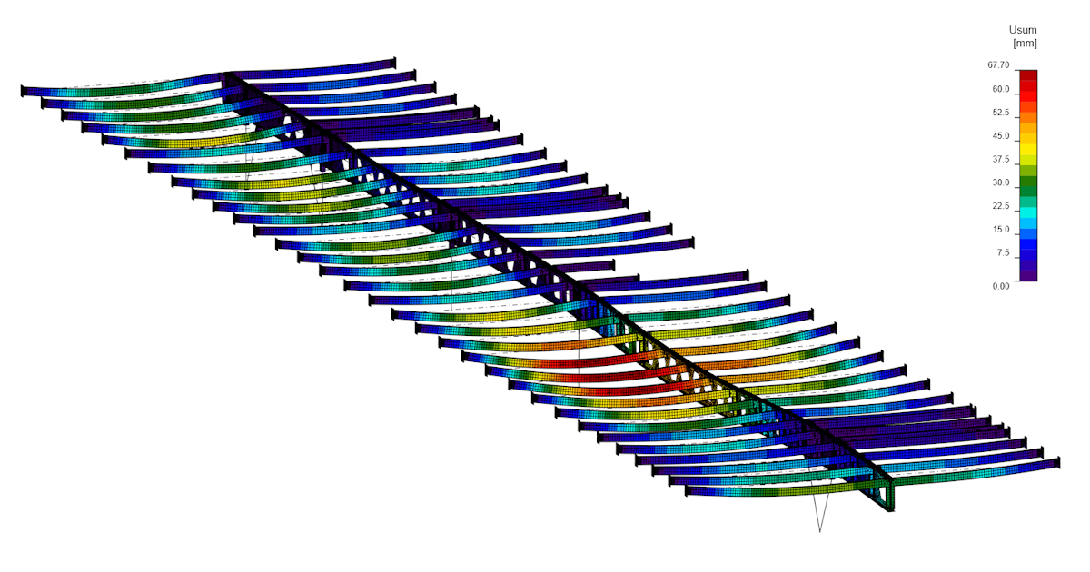
\[ \textsf{\textit{\footnotesize{Deflections on members from GMNIA analysis}}}\]
Results: Once the design was refined to a satisfactory level, the GMNIA analysis confirmed the final design's deformations, stresses, and plastic strains as acceptable.
\[ \textsf{\textit{\footnotesize{Visualization of the deformation under load}}}\]
Double-Check and Verification: To ensure accuracy, internal forces were compared between RSA and IDEA StatiCa Member, providing a double-check of the results.

Estonia
The engineers harnessed the capabilities of the IDEA StatiCa Member application, beginning with Linear Buckling Analysis (LBA) and progressing to Geometrically and Materially Nonlinear Analysis with Imperfections (GMNIA), the most advanced analysis type for static loading. In GMNIA, all potential imperfections—such as varying plate thickness, out-of-straightness, residual stresses, material non-homogeneities, and support misalignment—are represented by equivalent geometrical imperfections. These imperfections are set using buckling mode shapes calculated by LBA, with the user selecting the maximum amplitude of the buckling mode shape for the imperfection.
Additionally, engineer Karl Kimmel used the IDEA StatiCa Member application for Fire Design Analysis of the beams, leveraging the tool's full capabilities to ensure the structure met all fire safety requirements. This comprehensive analysis helped confirm the beams' performance under fire conditions, further strengthening the overall design.
Conclusion
The new educational center project in Tallinn is a testament to the power of advanced structural engineering and innovative design. By leveraging the capabilities of IDEA StatiCa, the engineering team at EstKonsult was able to overcome significant challenges and deliver a robust, flexible, and modern facility that meets the needs of the community. This project showcases the importance of using cutting-edge tools and techniques in combination with innovative engineering thinking in structural engineering to achieve ambitious architectural visions and ensure the safety and functionality of complex structures.
Try IDEA StatiCa for free


