Curved shear wall design
The design of such elements usually involves a lot of assumptions, engineering judgment, and a combination of hand calculations with dedicated software that would still not provide complete insight and code compliance. With IDEA StatiCa RCS, you can have a complete solution and design easily any cross-section with extensive code checks.
Preparing the model
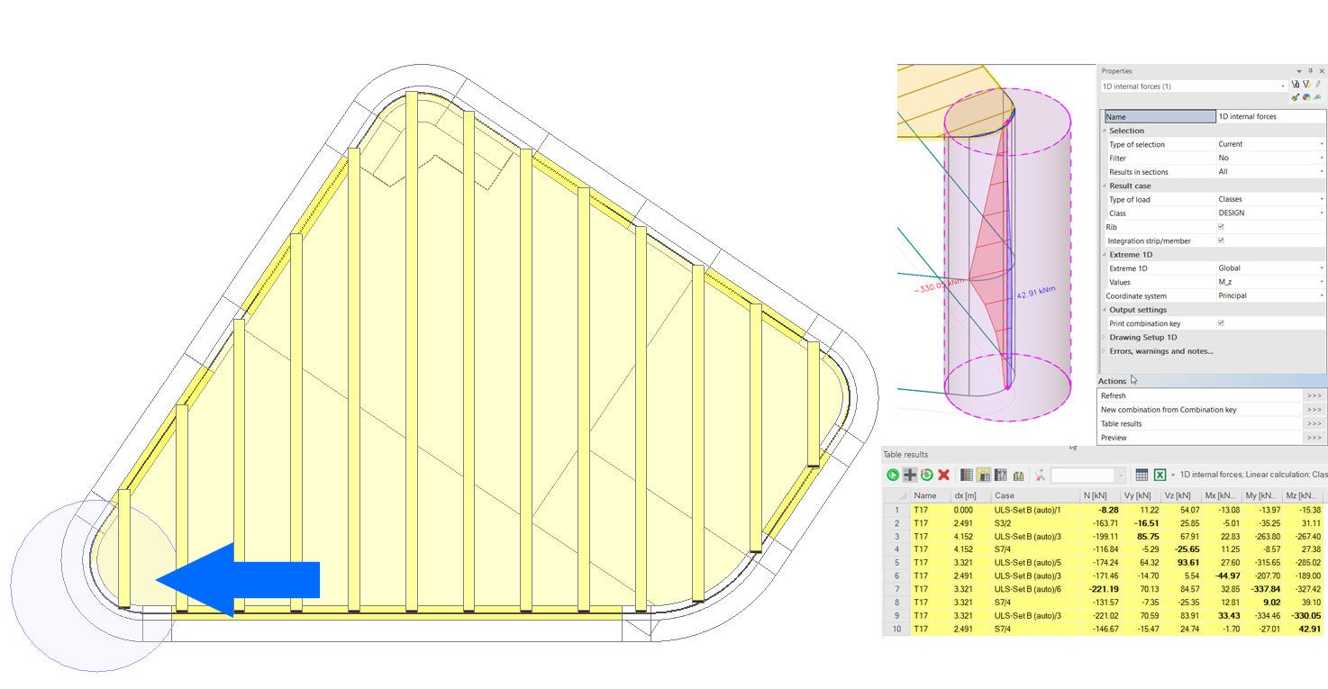
The customer has modeled & analyzed this project in SCIA Engineer, and although the curved walls do not pose a problem from a modeling perspective, in terms of design it is not as straightforward as it would be with typical 1D & 2D members. In this situation, it is necessary to use an integration strip (which essentially integrates 2D stress components and produces equivalent 1D member ones). This allows the designer to comply with the checks of the relevant code provisions.
After the analysis in SCIA Engineer, the results are presented in a tabulated format and can be directly exported to Excel or other software. In the image below, the critical components (in bold font), their locations and their combination are presented. Designing against multiple combinations is important as the section forces are not maximized simultaneously, allowing a more accurate, safe and economical solution to the problem. Moreover, when Serviceability checks are involved, it is very important to classify theses combinations as such to perform the relevant checks.
Top view with designed wall
Design process with IDEA StatiCa RCS
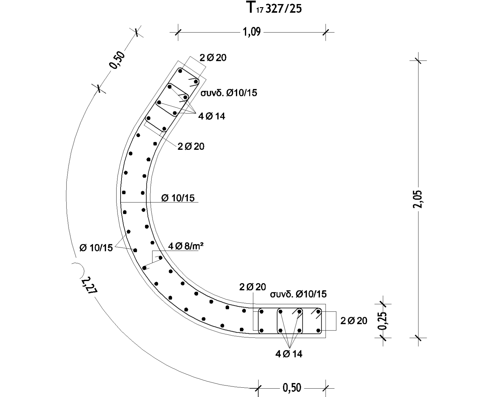
After exporting the results, we are moving to IDEA StatiCa RCS and recreate the curved cross-section geometry. To save time, we can simply import the geometry of the curved wall through a DFX file. Then, with the reinforcement tools of RCS, all rebars are placed in their exact location.
Reinforcement layout
The effective cross-section for biaxial shear
The next step is to import the section forces via a simple copy/paste procedure from the related table in SCIA Engineer. In this particular case, the ULS forces are imported, but, as can be seen in the table, there are multiple tabs allowing the definition of Accidental and other load combinations (Characteristic and Quasi-Static).
Combinations of load
Finally, the user can choose the checks that need to be conducted, from a multitude of options covering even specialist cases (prestressed members, bridge-related, container vessels, fire resistance, and fatigue). Once this is done, the user can examine a summary of the results for the chosen checks in the form of tables and failure modes and modify their appearance. Obviously, the user can export and present the results as documents with the press of a button.
Analysis results


