Welded Unreinforced Flange-Welded Web (WUF-W) Prequalified Connection - AISC
This verification example was prepared in a joint project between Ohio State University and IDEA StatiCa. The authors are listed below:
- Baris Kasapoglu, Ph.D. student
- Ali Nassiri, Ph.D.
- Halil Sezen, Ph.D.
3.1. Introduction
The third prequalified connection covered in this verification study is welded unreinforced flange-welded web (WUF-W) moment connection. In this chapter, similarly to the previous chapters, six experimentally investigated steel connections were selected from the literature to be compared their flexural moment strengths obtained using IDEA StatiCa and AISC design procedure. In addition, the moment-rotation comparison between IDEA StatiCa and ABAQUS was performed for one of the specimens selected as a baseline model.
3.2 Experimental Study
Ricles et al. (2000) conducted a series of experiments to investigate seismic performance of ductile welded unreinforced flange connections at Lehigh University. For this purpose, six exterior and five interior full-scale connections were subjected to cycling loading. Although the weld and geometric details of none of the tested specimens necessarily satisfy the requirements of the latest AISC 358 (2016), this experimental study was selected to be examined in this verification study because of the following reasons:
- There is no experimental investigation conducted in the U.S. for WUF-W with the specimens that satisfy all requirements outlined in AISC 358 (2016)
- Being one of the experimental studies that formed that basis of prequalification requirements of WUF-W moment connections in AISC 358 (2016)
- This experimental research was sponsored by SAC Joint Venture with funding from the Federal Emergency Management Agency (FEMA) to evaluate the improved details of WUF-W moment connections. SAC research program was implemented to improve the steel connection design and performance after poor performance was observed in some connections after the 1994 Northridge earthquake.
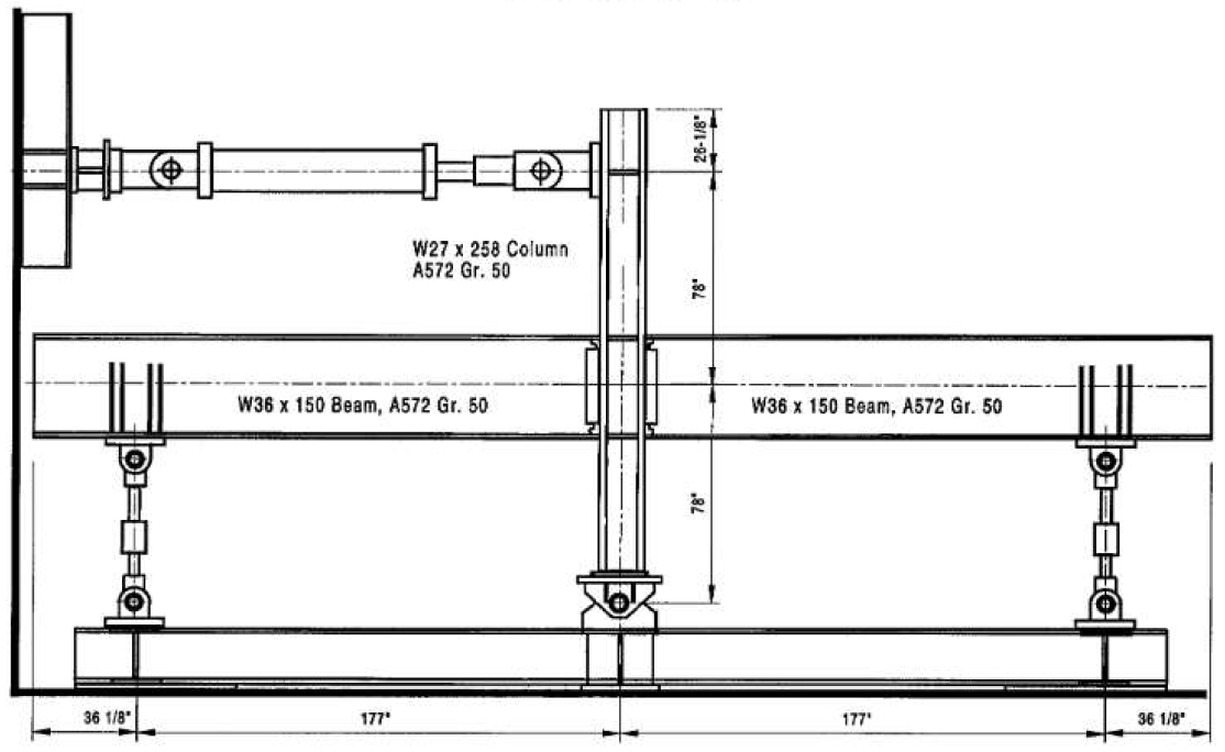
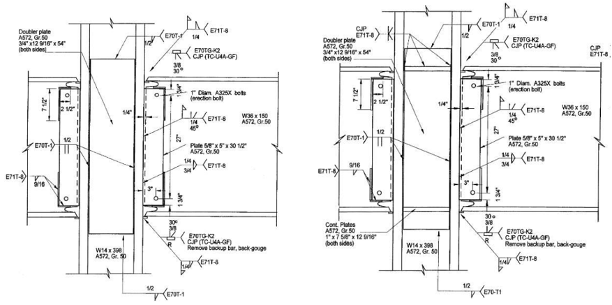
The test setup for interior connections is illustrated in Figure 3.1. The length between beam support and the column centerline was 177 in. (4.50 m), and the length from the actuator to the bottom support of the column was 156 in. (3.96 m). Among 11 tested connections, six of them were chosen to be covered in this verification study. The geometric and material properties of the selected six connections are presented in Tables 3.1 and 3.2, and the configurations of the specimens are shown in Figures 3.2 through 3.4.
Table 3.1: Properties of the WUF-W specimens
| Specimen No. | Beam | Column | Shear plate size (in.) | Doubler plate thickness (in.) | Continuity plate thickness (in.) |
| Baseline (T1) | W36x150 | W14x311 | 5/8x5x30.5 | - | 1.0 |
| T5 | W36x150 | W14x311 | 5/8x5x30.5 | 1/2 (one side) | - |
| C1 | W36x150 | W14x398 | 5/8x5x30.5 | 3/4 (both sides) | - |
| C2 | W36x150 | W14x398 | 5/8x5x30.5 | 3/8 (both sides) | 1.0 |
| C3 | W36x150 | W27x258 | 5/8x5x30.5 | 3/8 (both sides) | - |
| C4 | W36x150 | W27x258 | 5/8x5x30.5 | 3/4 (both sides) | 1.0 |
Figure 3.1: Test setup (Ricles et al., 2000)
Figure 3.2: Left) Configuration of baseline model T1; Right) configuration of Specimen T5 (Ricles et al., 2000)
Figure 3.3: Left) Configuration of Specimen C1; Right) configuration of Specimen C2 (Ricles et al., 2000)
Figure 3.4: Left) Configuration of Specimen C3; Right) configuration of Specimen C4 (Ricles et al., 2000)
Table 3.2: Measured material properties of the WUF-W specimens (Ricles et al., 2000)
| Specimen No. | Section | Yield stress (ksi) | Ultimate stress (ksi) |
| Baseline (T1) | Column (flange) | 47.3 | 69.5 |
| Beam (flange) | 55.1 | 71.6 | |
| Shear tab | 51.3 | 75.5 | |
| Continuity plate | 38.2 | 62.9 | |
| T5 | Column (flange) | 47.3 | 69.5 |
| Beam (flange) | 55.1 | 71.6 | |
| Shear tab | 51.3 | 75.5 | |
| Doubler plate | 53.0 | 72.0 | |
| C1 | Column (flange) | 53.2 | 72.4 |
| Beam (flange) | 56.7 | 72.5 | |
| Shear tab | 51.3 | 75.5 | |
| Doubler plate | 57.1 | 76.7 | |
| C2 | Column (flange) | 53.2 | 72.4 |
| Beam (flange) | 56.7 | 72.5 | |
| Shear tab | 51.3 | 75.5 | |
| Doubler plate | 57.1 | 76.7 | |
| Continuity plate | 53.0 | 70.9 | |
| C3 | Column (flange) | 50.2 | 73.3 |
| Beam (flange) | 55.1 | 71.6 | |
| Shear tab | 51.3 | 75.5 | |
| Doubler plate | 64.5 | 85.2 | |
| C4 | Column (flange) | 50.2 | 73.3 |
| Beam (flange) | 55.1 | 71.6 | |
| Shear tab | 51.3 | 75.5 | |
| Doubler plate | 64.5 | 75.5 | |
| Continuity plate | 64.5 | 85.2 |
The baseline model (specimen T1) and specimen T5 are exterior connections whereas the others are interior ones that consist of identical beams and connections attached to the same column from each horizontal side (see Figure 3.1). Since the identical connections showed almost the same performance during the testing, only one of their after-test photos and moment-rotation relationships are shared below for each interior specimen covered in this study (specimens C1, C2, C3, and C4).
The beam web of the baseline model was groove welded to the column flange and a supplementary weld was provided continuously around the edges of the shear tab. It was reported that the groove weld between the shear tab and column flange was cracked during 2% drift cycles, and beam flanges were cracked during 4% drift cycles as shown in Figure 3.5. Specimen T5 was designed differently from the baseline model with a doubler plate, a partial weld between the shear tab and beam web, a larger fillet weld size between the shear tab and column flange, and without a continuity plate. It was reported that the ductile fracture occurred in the beam flange during 6% cycles (see Figure 6).
Figure 3.5: Left) Baseline model (T1) after testing; Right) moment-total plastic rotation relationship (Ricles et al., 2000)
Figure 3.6: Left) Specimen T5 after testing; Right) moment-total plastic rotation relationship (Ricles et al., 2000)
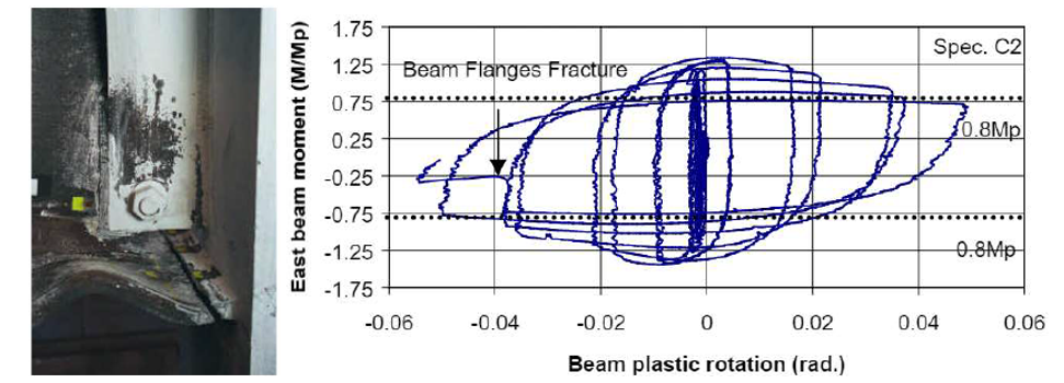
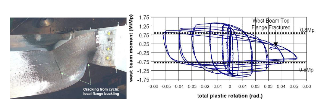
Specimen C1 was one of the four interior connections covered in this study. It had a larger column size and thicker doubler plate compared to specimen T5. Ductile fracture was observed at the first cycle of 5% drift on the west beam top flange and the second cycle of 5% drift on the east beam top flange illustrated in Figure 3.7., Specimen C2, differently from specimen C1, was designed with a continuity plate and with a thinner doubler plate. Experimental results showed that specimen C2 failed during cycles of 6% drift due to the ductile fracture on both beam flanges as shown in Figure 3.8.
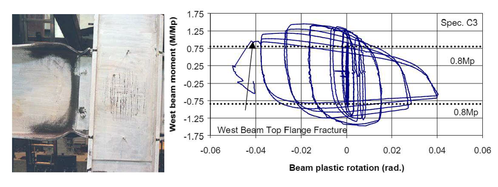
Specimen C3 consisted of a deeper and thinner column compared to the first four specimens. It was stated in the test report that the ductile fracture of west beam flange was observed during the first cycle of 5.5% story drift as shown in Figure 3.9. Specimen C4 had thicker doubler and continuity plates in addition to the configuration of specimen C3. During the experiment, ductile fracture occurred at the end of 6% drift cycle (Figure 3.10).
Figure 3.7: Left) Specimen C1 after testing; Right) moment-total plastic rotation relationship (Ricles et al., 2000)
Figure 3.8: Left) Specimen C2 after testing; Right) moment-total plastic rotation relationship (Ricles et al., 2000)
Figure 3.9: Left) Specimen C3 after testing; Right) moment-total plastic rotation relationship (Ricles et al., 2000)
Figure 3.10: Left) Specimen C4 after testing; Right) moment-total plastic rotation relationship (Ricles et al., 2000)
3.3 Code Design Calculations
The procedure outlined in Section 8.7 of AISC 358 (2016) for WUF-W connections were followed, and the following checks were performed for the six specimens.
- Check beam geometric limitations (AISC 358 Sec. 8.3.1)
- Check column geometric limitations (AISC 358 Sec. 8.3.2)
- Check beam design shear strength (AISC 358, Sec. 8.7)
- Check flexural strength (AISC 360, Eq. F2-1)
- Check continuity plate requirements (AISC 341, Sec.E3.6f.2)
- Check column-beam strength relationship (AISC 358 Section 8.4)
- Check beam flange to column flange welds (AISC 358 Section 8.5)
- Check weld access hole geometry (AWS D1.8/D1.8M)
- Check beam web-to-column connection (AISC 358 Section 8.6)
The summary of the AISC 358 (2016) design checks of the six specimens is presented in Table 3.3. The details of the design calculations and checks are provided in Appendices E and F.
Table 3.3: AISC 358 (2016) design checks for the specimens
| Design Checks | Baseline (T1) | T5 | C1 | C2 | C3 | C4 |
| Beam geometric limitations | OK | OK | OK | OK | OK | OK |
| Column geometric limitations | OK | OK | OK | OK | OK | OK |
| Beam design shear strength | OK | Not OK | Not OK | Not OK | Not OK | Not OK |
| Beam flexural strength | OK | OK | OK | OK | OK | OK |
| Continuity plate requirements | Not OK | - | - | Not OK | - | Not OK |
| Column-beam strength relationships | OK | OK | OK | OK | OK | OK |
| Beam flange-to-column flange connection | OK | OK | OK | OK | OK | OK |
| Weld access hole geometry | Not OK | Not OK | Not OK | Not OK | Not OK | Not OK |
| Beam web-to-column connection | Not OK | OK | OK | OK | OK | OK |
| Panel Zone | OK | OK | OK | Not OK | OK | OK |
It is assumed that plastic hinge occurs at the face of the column in accordance with Section 8.7 in AISC 358 (2016). The moment strength of the beam at plastic hinge location, \(M_{by@ph}\), can be calculated using Equation 3.1.
\(M_{by@ph}\) = \(F_{yb}Z_{bx}\) (3.1)
where \(F_{yb}\) is yield stress of beam, \(Z_{bx}\) is plastic section modulus of beam. The plastic moment capacities of the specimens were calculated and presented in Table 3.4.
Table 3.4: Plastic moment capacities of the specimens calculated following AISC design procedure
| Specimen No. | Plastic moment capacity (kips-in.) |
| Baseline | 32,013 |
| T5 | 32,013 |
| C1 | 32,943 |
| C2 | 32,943 |
| C3 | 32,013 |
| C4 | 32,013 |
3.4 IDEA StatiCa Analysis
The selected six specimens were modeled in IDEA StatiCa with the aim of simulating the behavior of the experiments. Their moment capacities and failure modes were identified using stress-strain analysis type (i.e., EPS). The measured material properties given in Ricles et al. (2000) (see Table 3.2) were introduced to the software, and resistance factors were set to 1.0. Using the connection stiffness analysis type (i.e., ST) in IDEA StatiCa, the moment-rotation relationship was calculated for the baseline model.
3.4.1 Analysis of Baseline Model
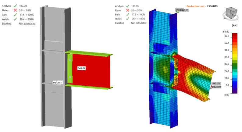
IDEA StatiCa model was developed for the baseline model. The measured material properties were introduced, and the overstrength coefficients, \(R_{y}\) and \(R_{t}\), were set equal to 1.0 (see Figure 3.11). Also, all LRFD resistance factors were set to 1.0 to compare the calculated actual response of the connections with that measured during the laboratory experiment (Ricles et al., 2000). To obtain the loads at the column centerline, a beam-column frame model was developed in SAP2000 using the lengths of column and beam in the test setup. Pin support was used at the bottom of the column and roller support was used at the end of the beam.
To calculate the moment capacity of the baseline model, an incremental loading was applied using stress, strain analysis (i.e., EPS) with “loads in equilibrium” option in IDEA StatiCa model until any of following was achieved:
- 5% of plastic strain in plates
- 100% strength capacity in bolts
- 100% strength capacity in welds
The weld between the shear tab and column flange reached its strength capacity when the shear force and the corresponding moment values were 167.70 kips and 29,700 kips-in., respectively (Figure 3.11). Using “ST” analysis, the moment-rotation relationship was obtained and is shown in Figure 3.12.
Figure 3.11: IDEA StatiCa model for baseline model
Figure 3.12: Moment-rotation relationship for the baseline model
3.4.2 Analysis of Variation Specimens
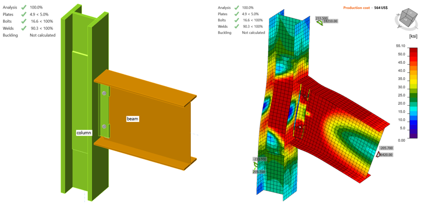
IDEA StatiCa analysis was performed for specimen T5 following the procedure explained for the baseline model. It was observed that the beam web reached 5% plastic strain when the shear force and the corresponding moment were 205.70 kips and 36,420 kips-in., respectively (Figure 3.13).
Figure 3.13: IDEA StatiCa model for Specimen T5
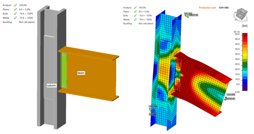
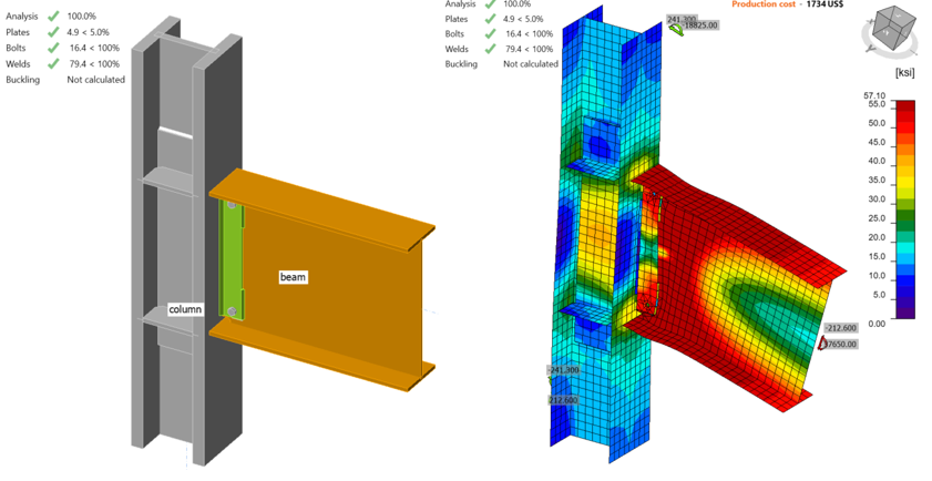
Specimen C1 was modelled and analyzed in IDEA StatiCa following the same procedure. It was observed that the beam web reached 5% plastic strain when the shear force and the corresponding moment were 212.60 kips and 37,650 kips-in., respectively (Figure 3.14).
Figure 3.14: IDEA StatiCa model for Specimen C1
Following the same procedure described in this section, IDEA StatiCa analysis was performed for specimen C2. It was observed that the beam web reached 5% plastic strain when the shear force and the corresponding moment were 212.60 kips and 37,650 kips-in., respectively (Figure 3.15).
Figure 3.15: IDEA StatiCa model for Specimen C2
Following the same procedure, IDEA StatiCa analysis was performed for specimen C3. It was observed that the beam web reached 5% plastic strain when the shear force and the corresponding moment were 213.20 kips and 37,750 kips-in., respectively (Figure 3.16).
Figure 3.16: IDEA StatiCa model for Specimen C3
Following the same procedure, IDEA StatiCa analysis was conducted for specimen C4. It was observed that the beam web reached 5% plastic strain when the shear force and the corresponding moment were 213.60 kips and 37,820 kips-in., respectively (Figure 3.17).
Figure 3.17: IDEA StatiCa model for Specimen C4
The six specimens were analyzed using IDEA StatiCa and their moment capacities at the column centerline were calculated by representing their test conditions. To compare the moment capacities with the ones calculated following the AISC 358 procedure, the moment capacities at the column face were calculated using Eq. 3.6 and presented in Table 3.5.
\(M_{y@foc}\) = \(M_{y@cc} + V\frac{d_{c}}{2}\) (3.6)
where \(M_{y@foc}\) is moment capacity at the column face, \(M_{y@cc}\) is moment capacity at the column centerline, \(V\) is shear force, and \(d_{c}\) is depth of column.
Table 3.5: Moment capacity calculated by IDEA StatiCa
| Specimen No | (kips) | (in.) | (kips-in.) | (kips-in.) |
| Baseline (T1) | 167.70 | 17.1 | 29,700 | 28,266 |
| T5 | 205.70 | 17.1 | 36,420 | 34,662 |
| C1 | 212.60 | 18.3 | 37,650 | 35,705 |
| C2 | 212.60 | 18.3 | 37,650 | 35,705 |
| C3 | 213.20 | 29.0 | 37,750 | 34,659 |
| C4 | 213.60 | 29.0 | 37,820 | 34,723 |
3.5. ABAQUS Analysis
In this section, the baseline model developed in Section 3.4.1 was constructed again using ABAQUS software (version 2022) for FE analysis and results were compared with IDEA StatiCa. The CAD model for the FE analysis was generated using the IDEA StatiCa’s viewer platform. The two bolts and 5 weld lines (i.e., between the shear tab-beam web and shear tab-column flange) were then added manually to the assembly using the CAD interface in ABAQUS. The vertical load of 182.2 kips and the corresponding moment of 32,270 kips-in. (around Y axis) were applied to a defined reference point (i.e., RF1) at the column centerline as shown in Figure 3.18. The analytical length of the column in IDEA StatiCa was 215.45 in. Therefore, to mimic the identical column length in ABAQUS, two other reference points (i.e., RF2 and RF3) were introduced 107.725 in. away from the center of the column along the Z axis in both directions (see Figure 3.18). These two reference points were fixed in all directions and were connected to the top and bottom faces of the column using the connector builder module in ABAQUS. In ABAQUS, the element size was chosen to be between 0.1–0.25 in. after mesh sensitivity analysis and a total of 240,417 elements were generated. The 3D stress, 8-node linear brick reduced integration (i.e., C3D8R ) was selected as element type.
Figure 3.18: Model setup in ABAQUS
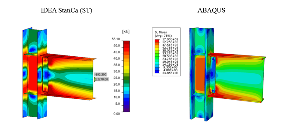
The tie constraint was applied between the weld lines and the attaching parts. The material behavior was modeled using bi-linear plasticity in ABAQUS. Other parameters, including density, elastic modulus, and Poisson’s ratio were taken from the IDEA StatiCa materials library. The numerical simulation was carried out on four processors (Intel Xenon (R) CPU E5-2698 v4 @ 2.20GHz) and took approximately 155 minutes to finish. Figure 3.19 compares the predicted von-Mises stress between IDEA StatiCa and ABAQUS.
Figure 3.19: Comparison of the calculated von Mises stress between IDEA StatiCa and ABAQUS models
The maximum predicted stress in IDEA StatiCa was 55.90 ksi on the beam top flange (note that the IDEA StatiCa legend shows the design data) while the ABAQUS model shows a maximum stress of 56.5 ksi at the same location. The maximum stress of 57 ksi in the ABAQUS legend belongs to the front long weld line connecting the shear tab to the column. The slightly different stress distribution is likely due to the consideration of the length of the column in ABAQUS and the way that boundary conditions have been applied, utilization of finer mesh in the FE analysis, and the simplified CAD model in IDEA StatiCa. Note that the authors performed a routine mesh sensitivity analysis for the IDEA StatiCa model as well and some inconsistencies in the results were observed.
Figure 3.20: Comparison of the calculated plastic strain between IDEA StatiCa and ABAQUS models
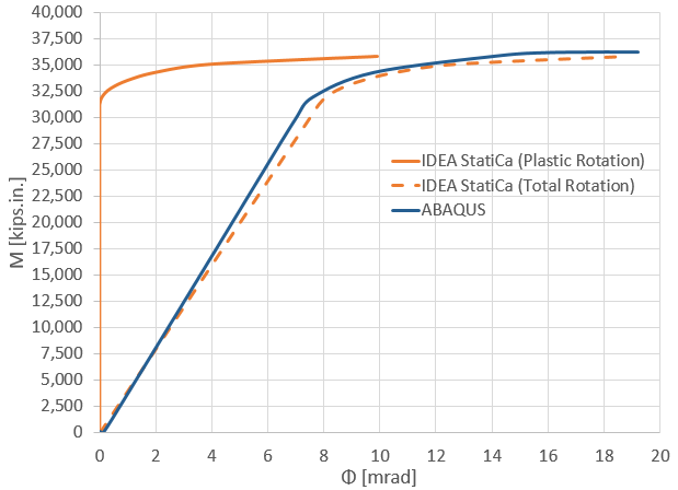
The maximum calculated plastic strain in IDEA StatiCa and ABAQUS were 10.8% and 11%, respectively (both on the front weld line connecting the shear tab to the column). Also, the predicted plastic deformation region by IDEA StatiCa was consistent with the calculated yield map in ABAQUS (i.e., the bottom row in Figure 3.20). Figure 3.21 depicts the comparison of the moment-rotation curve between the two software with respect to the column centerline. Note that in Figure 3.21, to obtain the total rotation by IDEA StatiCa (shown by dashed orange line), the linear beam rotation at the column centerline was calculated using SAP2000 and then added to the default plastic rotation curve reported by IDEA StatiCa (shown by solid orange line). Both models offer comparable initial stiffness estimations. The minor discrepancy could be associated with the difference in the element types (i.e., solid element in ABAQUS versus shell element in IDEA StatiCa) and the employment of the tie constraint in ABAQUS to represent the welds.
Figure 3.21: Moment-rotation comparison between IDEA StatiCa and ABAQUS
3.6 Summary and Comparison of Results
Experimental observations indicate that the baseline model failed due to the fracture occurred in the weld between the beam web and column flange. Similarly, IDEA StatiCa analysis indicated that the weld failed between the shear tab and column flange. Also, AISC design checks showed that this weld did not satisfy the beam web-to-column connection limitations outlined in Section 8.6 in AISC 358 (2016) (see Table 3.3). Moment-plastic rotation relationships measured during the experiment and computed using IDEA StatiCa analysis for the baseline model are compared in Figure 3.22. The moment capacity calculated following the AISC procedure at the column face was transferred to the column centerline using Eq. 3.6 since the moment-rotation comparison was performed at the column centerline, and it is shown in the same graph with the one calculated using IDEA StatiCa stress-strain analysis (Figure 3.5).
Figure 3.22: Moment-rotation comparison
Regarding the variation specimens (see Section 3.2), it was observed in the experimental study (Ricles et al., 2000) that the specimens failed due to severe local buckling and fracture in the beam flanges (Figures 3.6 through 3.10). Similarly, IDEA StatiCa analysis showed that specimens T5, C1, C2, C3, and C4 reached their capacities at beam web that reached 5% plastic strain limit (Figures 3.13 through 3.17). On the other hand, based on the AISC design checks, failure was expected to occur in the beam although some of the checks were not fully satisfied (e.g., continuity plate and weld access hole in Table 3.3). This is because of a slight difference in geometric requirements. The moment capacity of all specimens calculated using IDEA StatiCa (Table 3.5) and following AISC procedure (Table 3.4) are presented in Figure 3.23.
All moment strengths calculated from IDEA StatiCa (using actual or measured properties) are approximately 8% larger than those from AISC, except for the baseline model. This is reasonable because the AISC moment strength, \(M_{p}\), are based on the design assumption that plastic hinge location is taken at the column face according to Section 8.7 in AISC 358 (2016). On the other hand, FEMA (2000) recommends plastic hinge location to be taken at half of the beam depth away from the column face for WUF-W moment connections. If the plastic hinge location was assumed to be a certain distance away from the column face, the additional moment due to the shear force on the plastic hinge to the column face should have been considered, thus larger moment capacities would have been calculated. The difference between the moment capacities calculated following AISC design procedure and using IDEA StatiCa can be attributed to the conservative assumption of AISC 358 for plastic hinge location of WUF-W moment connections.
Figure 3.23: Moment capacity calculated by IDEA StatiCa and AISC procedure
Read the full study on prequalified connections!
References
AISC (2016), “Prequalified Connections for Special and Intermediate Steel Moment Frames for Seismic Applications, including Supplement No. 1,” American Institute of Steel Construction ANSI/AISC 358-16, Chicago, Illinois.
Ricles, J.M., Mao, C., Lu, L.W. and Fisher, J.W. (2000), “Development and Evaluation of Improved Details for Ductile Welded Unreinforced Flange Connections,” Report No. SAC/BD-00-24, SAC Joint Venture, Sacramento, CA.
FEMA (2000), Recommended Seismic Design Criteria for New Steel Moment-Frame Buildings, FEMA 350, Federal Emergency Management Agency, Washington, DC.


