Code-check of concrete block according to Canadian standards
The concrete below the base plate is simulated by Winkler subsoil with uniform stiffness, which provides the contact stresses. The average stress at the loaded area in contact with the base plate is used for compressive check.
Concrete in compression
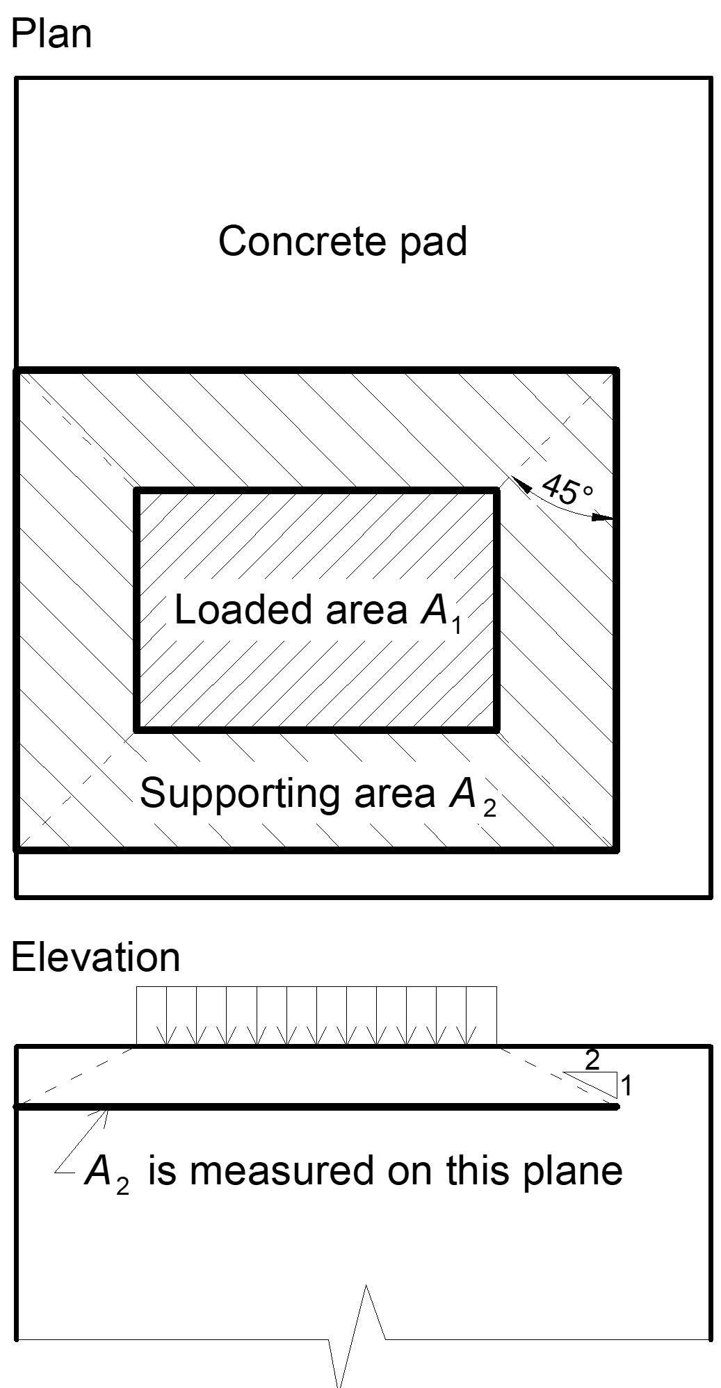
The concrete design bearing strength in compression is determined in accordance with S16-14 – 25.3.1 and CSA A23.3 – 10.8. When the supporting surface of the concrete is larger than the base plate the design bearing strength is defined as
\[ f_{p,(max)} = 0.85 \phi_c f'_c \sqrt{\frac{A_2}{A_1}} \le 1.7 \phi_c f'_c \]
where:
- ϕc=0.65 – resistance factor for concrete
- f'c – concrete compressive strength
- A1 – base plate area in contact with a concrete surface (upper surface area of the frustum)
- A2 – concrete supporting surface (geometrically similar lower area of the frustum having its slopes of 1 vertical to 2 horizontal)
The assessment of concrete in the bearing is as follows:
σ ≤ fp(max)
where:
- σ – average compressive stress under the base plate
Transfer of shear forces
Shear loads can be transferred via one of these options:
- Shear lug,
- Friction,
- Anchor bolts.
Shear lug
Shear loads are considered to be transferred only via shear lug. Concrete bearing is not checked in software and should be checked by the user elsewhere. Shear lug and welds are checked using FEM and weld components.
Friction
In the case of compressive force, the shear loads can be transferred via friction between a concrete pad and a base plate. The friction coefficient is editable in the Code setup.
Anchor bolts
If the shear load is transferred via anchor bolts only, the shear force acting on each anchor is determined by FEA and anchor bolts are assessed according to ACI 318-14 as described in the following chapters.

