Stiffness analysis (AISC)
1 New project
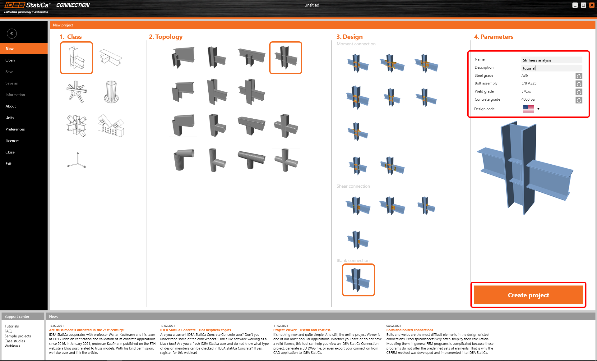
Start with launching the IDEA StatiCa Connection. Create a new project by selecting a starting template closest to the desired design, fill the name and choose AISC design code and default steel grade – A36.
Since you work under the AISC code, make sure to set the imperial units (see How to change the system of units).
2 Geometry
You start with defining Geometry. Three beams were automatically added.
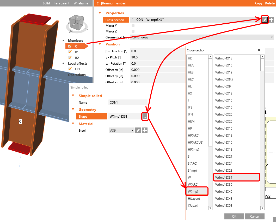
You change the cross-sections of member C to W(Imp)8X31.
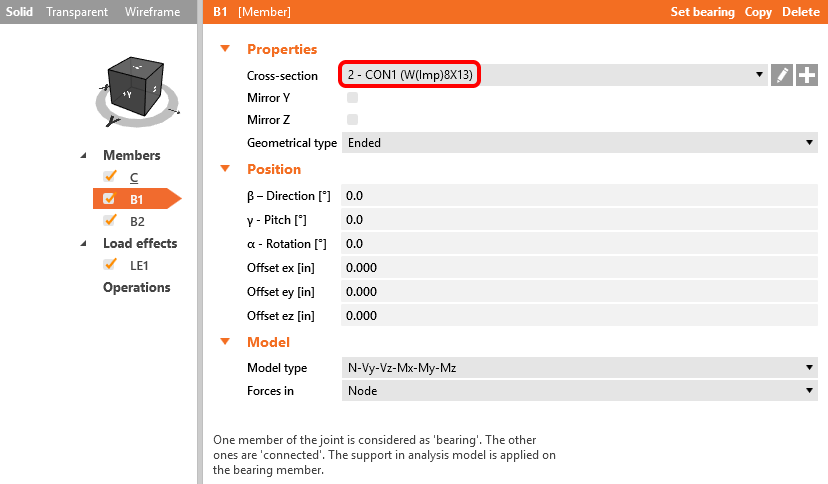
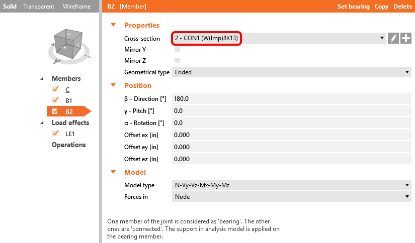
Next, you modify cross-sections of members B1 and B2 to W(Imp)8X13.
3 Load effects
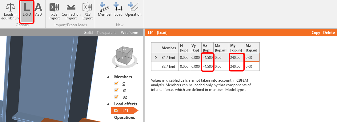
You can continue with Load effects. You input values of forces into the table and set the AISC-LRFD design code. More load cases can be added.
4 Design
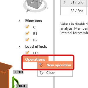
You will define a set of manufacturing operations to model connections between members. Start with the right mouse button click at the Operations row in the tree of entities in the 3D scene. We choose the New operation command from the context menu.
In the dialogue with all available manufacturing operations, you will choose the Endplate operation.
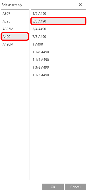
And proceed with the choosing of the desired bolt assembly, the A490 5/8.
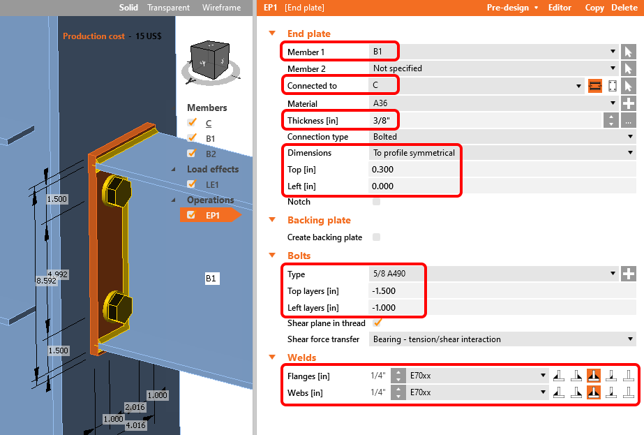
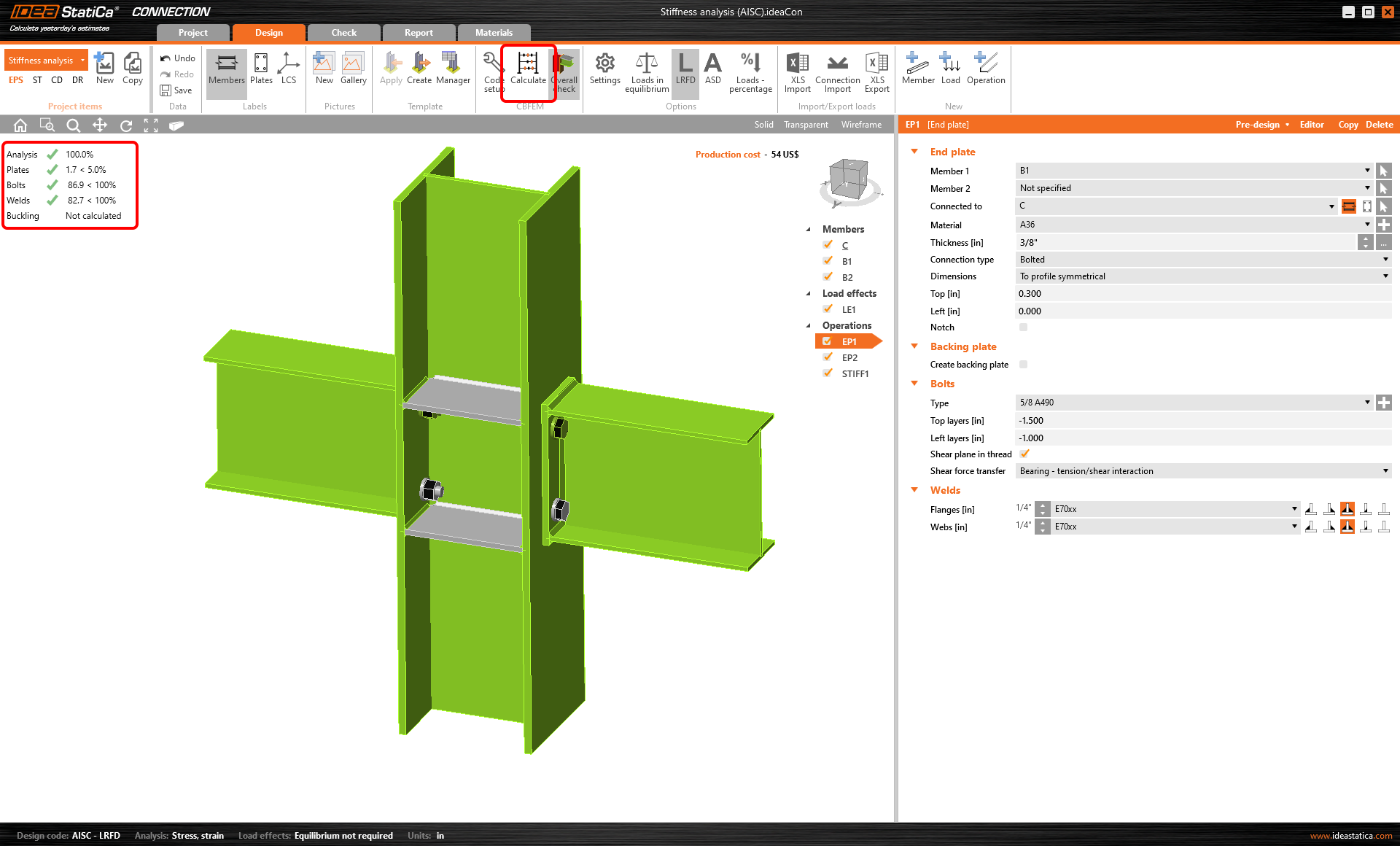
Now you have to define the right properties for creating the desired connection. Follow the values in the picture below.
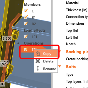
Copy operation EP1. With the right mouse button click at the EP1 and choose Copy.
Now you have to set the correct member for EP2.
You can add the next new operation with the right mouse button. Click at the Operations row in the tree of entities in the 3D scene. You choose the New operation command from the context menu.
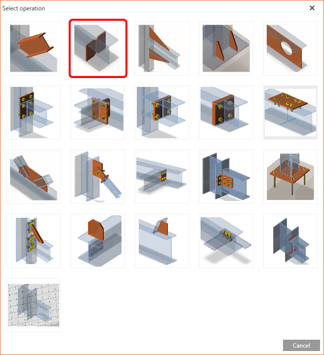
In dialogue with all available manufacturing operations, you will choose the Stiffener operation.
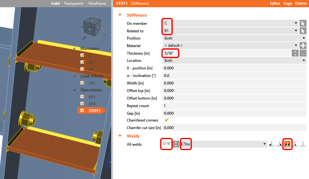
Now you need to modify the manufacturing for operation STIFF1.
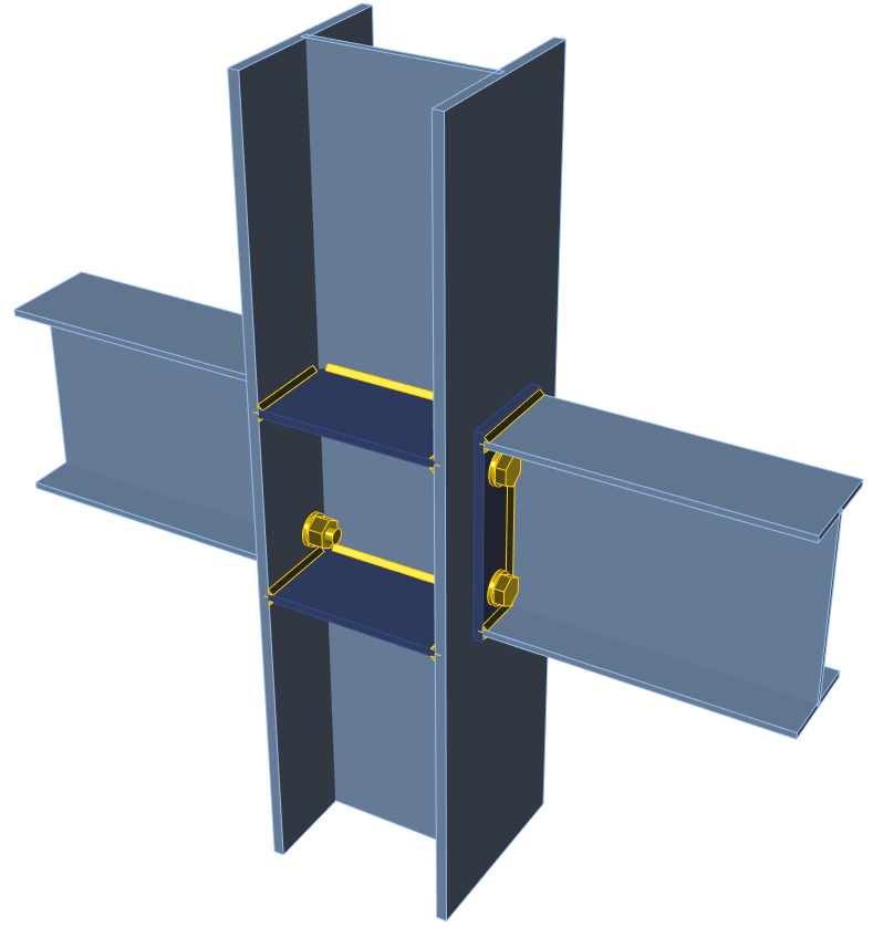
Let’s check the final design of the joint.
5 Stress/strain analysis
To have the complete picture of the connection behavior, the stress/strain analysis is run first.
Select Calculate in the ribbon to run the analysis based on the CBFEM method. The numerical model is automatically generated, the calculation is performed and you can directly see the overall check results in the top-left corner of the scene.
More detailed results can be displayed in the Check tab: activate the Strain check, Bolt forces, Mesh and Deformed shape of the connection in the ribbon to get a full picture of what is happening in the joint.
6 Stiffness analysis
To keep the stress/strain results, copy this project item.
In the copied project item, change the analysis type to Stiffness (ST) in the top ribbon.
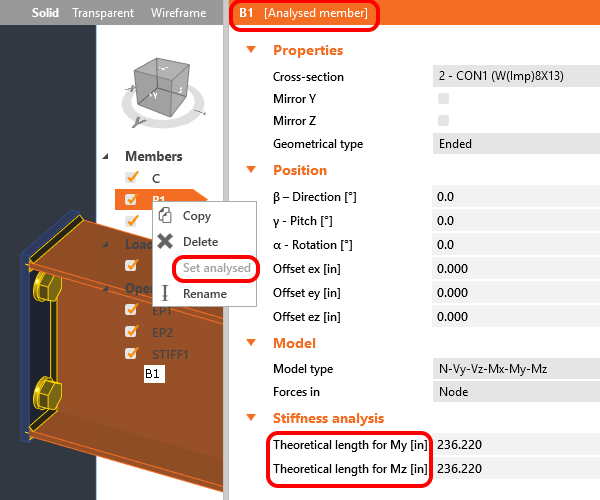
Verify that beam B1 is set as an Analysed member as shown below. (If you want switch Analysed member, you can use right mouse button and set another member as an Analysed member).
The “Theoretical length for My, Mz” can be set for the analyzed member. For more information about the theoretical length, please see Theoretical background and Video – tips for stiffness analysis.
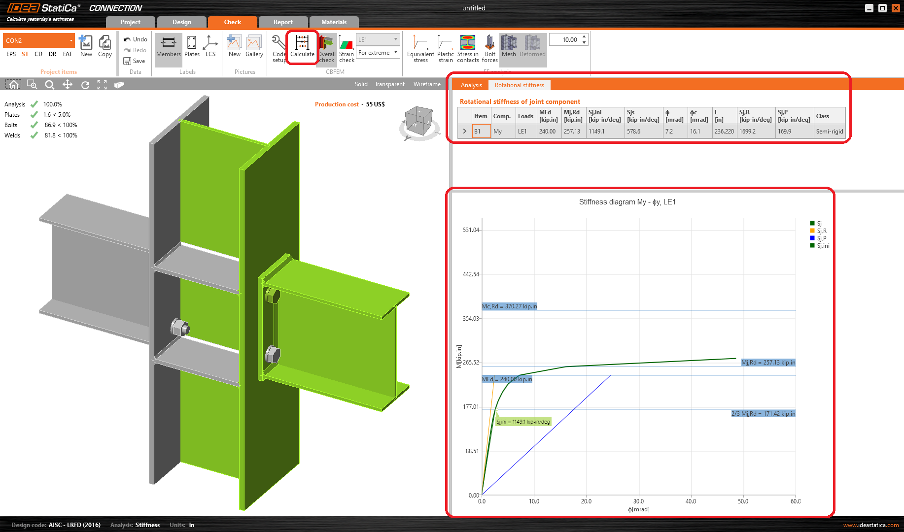
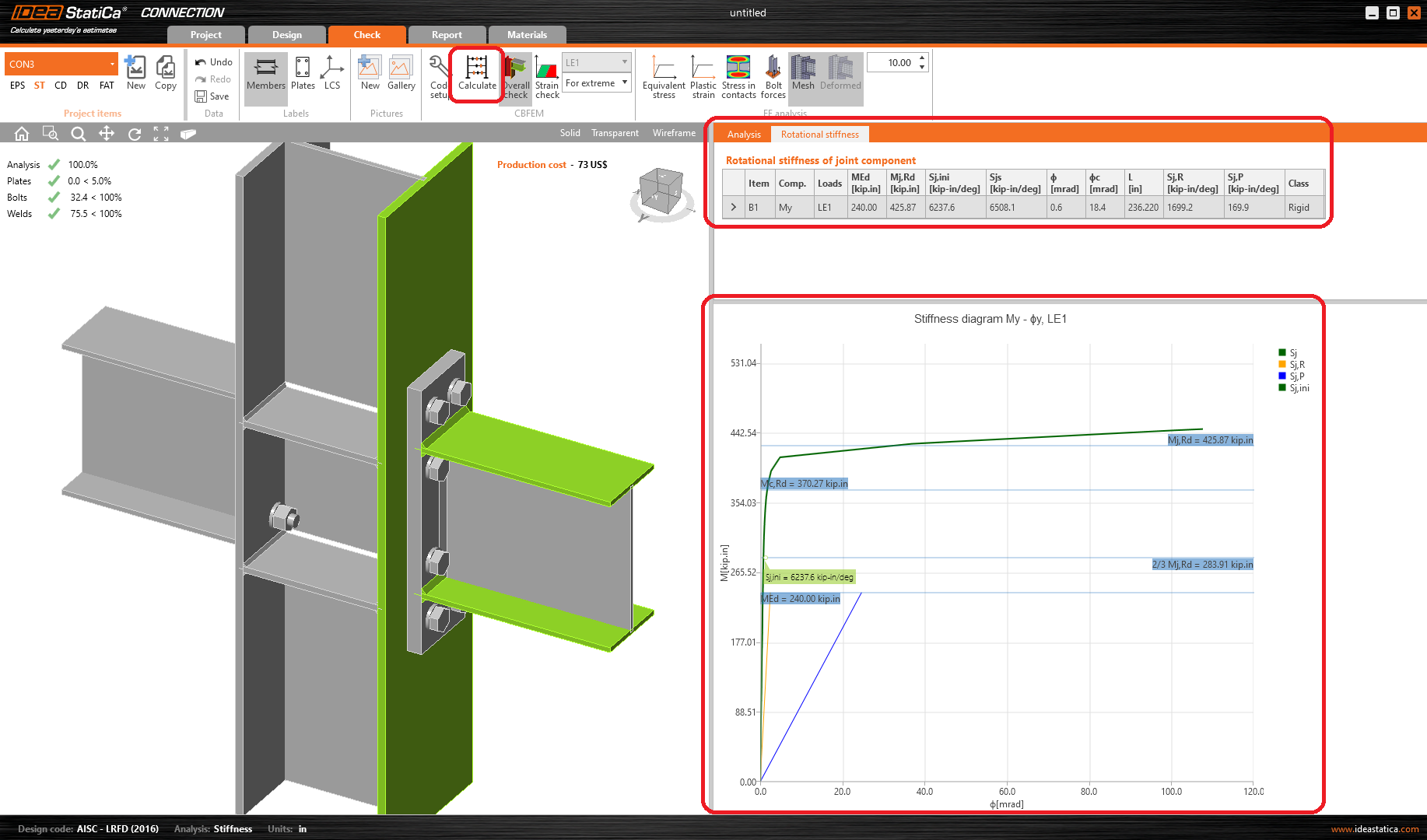
Start the stiffness analysis by the Calculate button in the top ribbon.
The result of the analysis and the load path can be checked in detail in the Rotational stiffness tab. For a better understanding of the results, see the Theoretical Background.
7 Modification of connection
To keep the project CON2, copy it and create CON3.
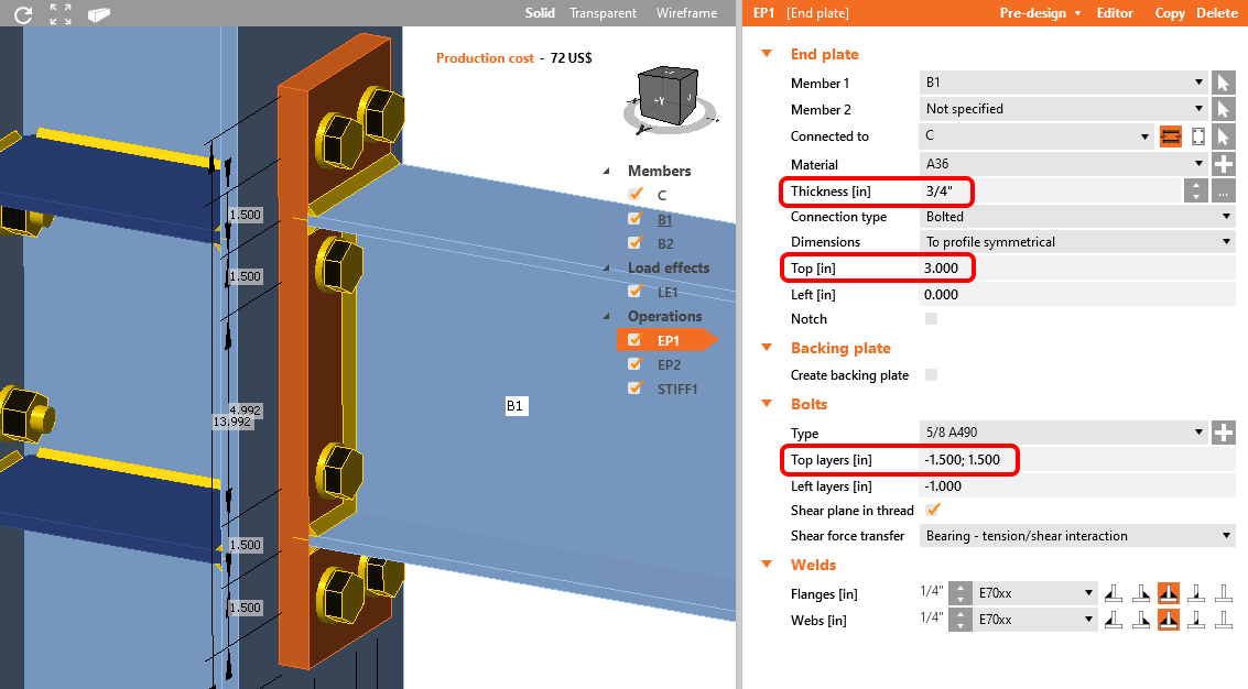
Modify endplate EP1 to increase the rigidity of the connection CON3.
Now run stiffness analysis again by icon Calculate from the top ribbon. And you can notice the change in results from Semi-rigid to Rigid.
For more information on stiffness analysis, please check out our Theoretical background.
8 Report
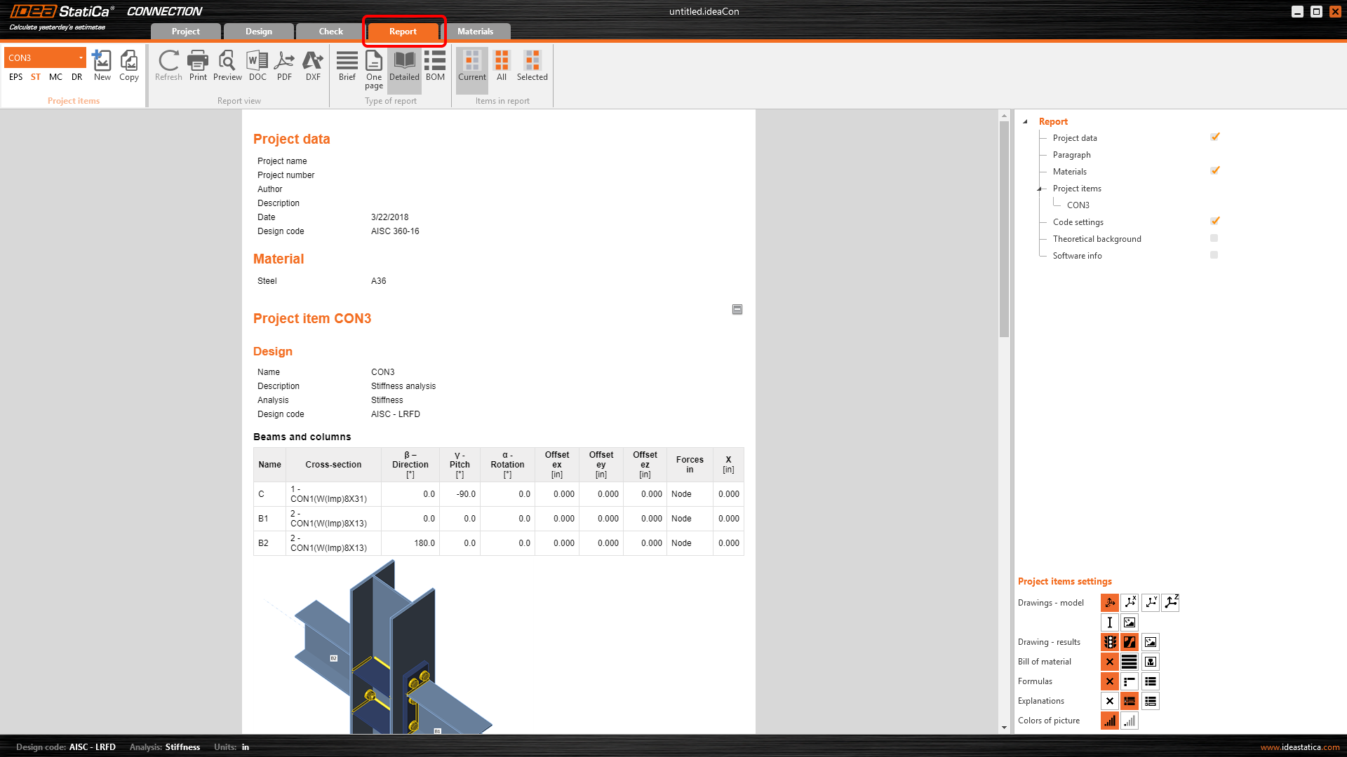
At last, go to the Report tab. IDEA StatiCa offers a fully customizable report to print out or save in an editable format.
You have designed, code-checked and calculated stiffness of the connection according to AISC.

