Robot Structural Analysis BIM link for concrete design
1 How to activate the link
- Download and install (as administrator) the latest version of IDEA StatiCa
- Make sure that you are using the supported version of Robot Structural Analysis
IDEA StatiCa automatically integrates the BIM link into your CAD/CAE software during its installation. You can check the status and activate more BIM links for later installed software in the BIM link installer.
Open IDEA StatiCa and navigate to the panel BIM and open the BIM link installer. A notification "Run as administrator" may appear, please confirm with the Yes button.
Select the software to integrate the IDEA StatiCa BIM link, click the Install button and check the Installed status.
2 How to use the link
First, download the source folder and open Model-Concrete hall.rtd in RSA and run the linear analysis. Select beams 1 and 2 (64 and 75 in RSA) and open the plug-in via Add-Ins→IDEA StatiCa→Beam.
Create a New project and select the EN (Eurocode) to follow.
To continue the export process, press the Next button. Do not change the folder to save the project. If you selected a different path, the Code-check manager wouldn’t be able to see and manage the exported items.
Select the Straight beam loaded in vertical plane and add Supports. Such settings will limit the calculation to 2D and it will not be possible to apply forces in the other plane.
Select Pre-fabricated concrete beam, specifically Prestressed precast beam with the option of subsequent post-tensioning.
Self-weight will be generated automatically based on the cross-section. You just add the Permanent load of –4 kN/m and at this point, you set the variable load to zero.
Standardly, only the variable load cases (not affecting the rheology of the structure) are exported. You add two variable load cases: SNOW and LIVE LOAD. These two cases will be exported as user-defined internal forces (My, Vz, N) from the global analysis.
Now, you can set the particular stages of construction: the beam will be prestressed in 5 days (PRE switch). In the stage of Storage and Transport, the supports will be shifted 2 m from the edge of the beam (values L1 and L2) and there will be 1 additional support in the middle (value n). The Final supports (next stage) will be at a distance of 28 m. The Superimposed dead load will be applied in 40 days.
3 IDEA StatiCa Beam project
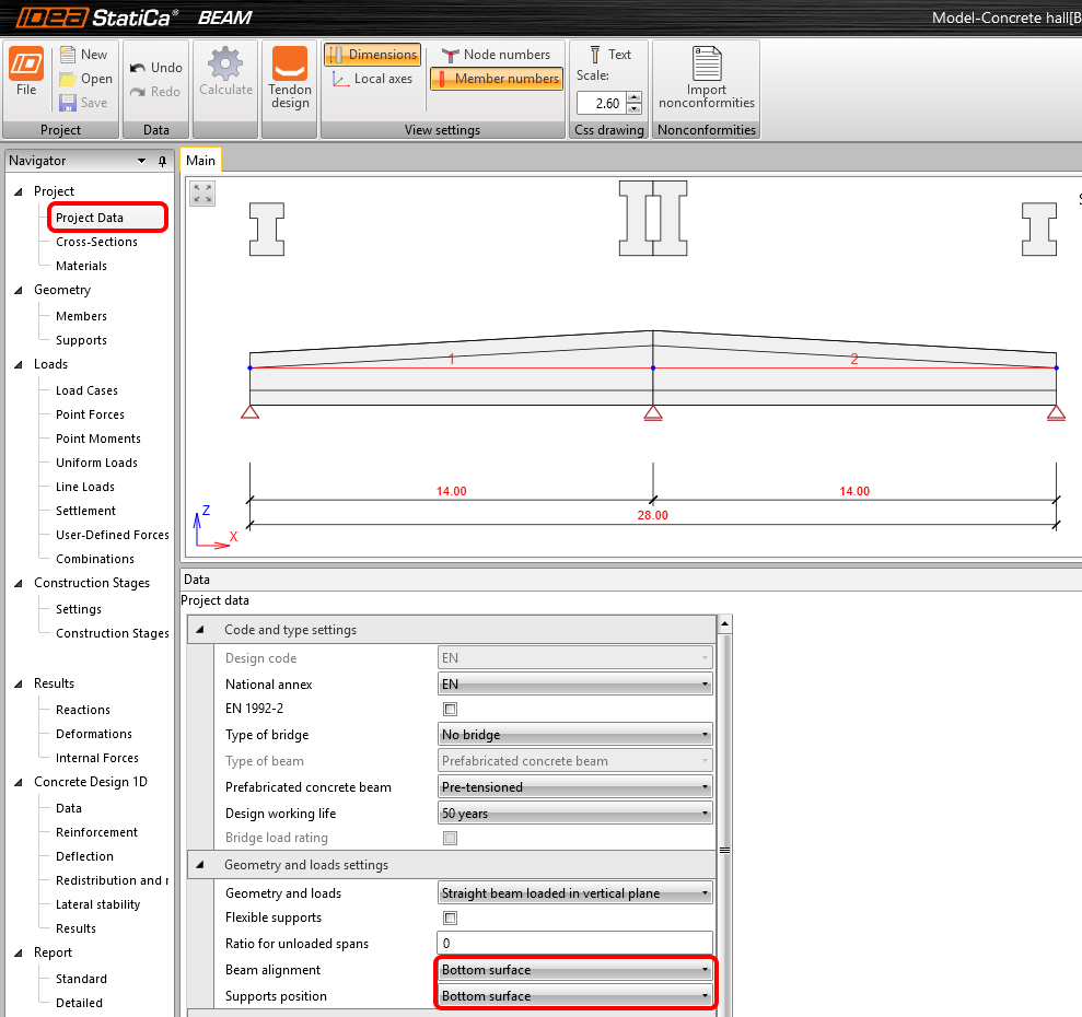
In Project Data, you align the beam and the position of supports to the bottom surface.
Materials
The concrete grade is imported from the FEM software automatically. Nevertheless, in our example, the grade imported from RSA (C25/30) is not sufficient for prestressed members, therefore, you change it directly in IDEA StatiCa Beam (Materials) to C40/50.
Load cases
The variable loads were automatically assigned to exclusive load cases. It means that they will not be combined together (only one of them can enter one combination).
Combinations
EN combinations 6.10 a,b were generated automatically by the application. Nevertheless, you need to add the variable load cases into the appropriate construction stage. You Edit (2) the variable load cases (3) into all of the ULS and SLS combinations of the End of the working life stage.
Now, you can move to the Tendon design by the button in the top ribbon.
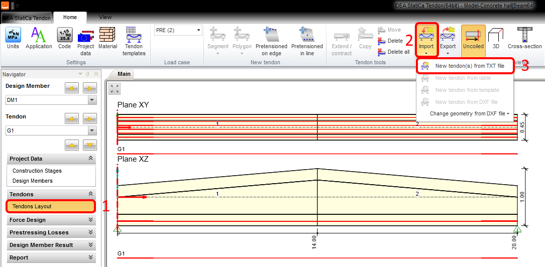
In the left tree, you open Tendons – Tendons Layout.
Now, you can import the prepared templates. Press Import – New tendon(s) from TXT file and load Prestressing tendons.nav from the source folder.
All the prestressing parameters are already set in the template.
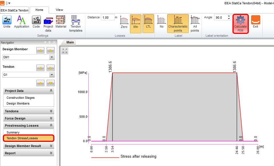
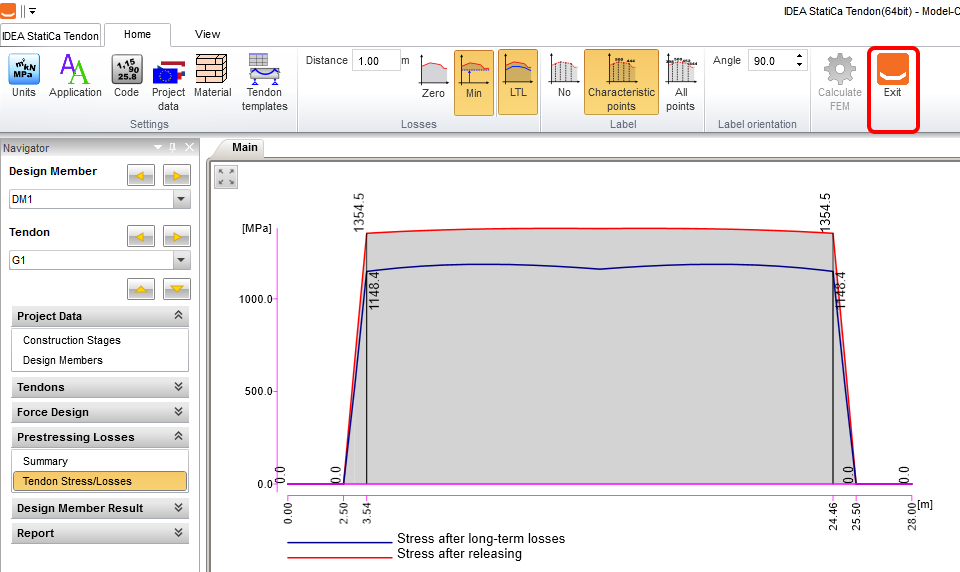
You can run the calculation of prestressing losses. Open Prestressing Losses – Tendon Stress/Losses in the left tree and press Calculate FEM.
You Exit the module once the analysis is finished.
Internal Forces
You can display the diagrams of internal forces in each of the construction stages. In the menu in the top ribbon, you can switch between stages and combinations. The figure below presents the internal forces from ULS combination in stage 7: End of the working life.
In each stage, you can see the extreme internal forces and the corresponding combination.
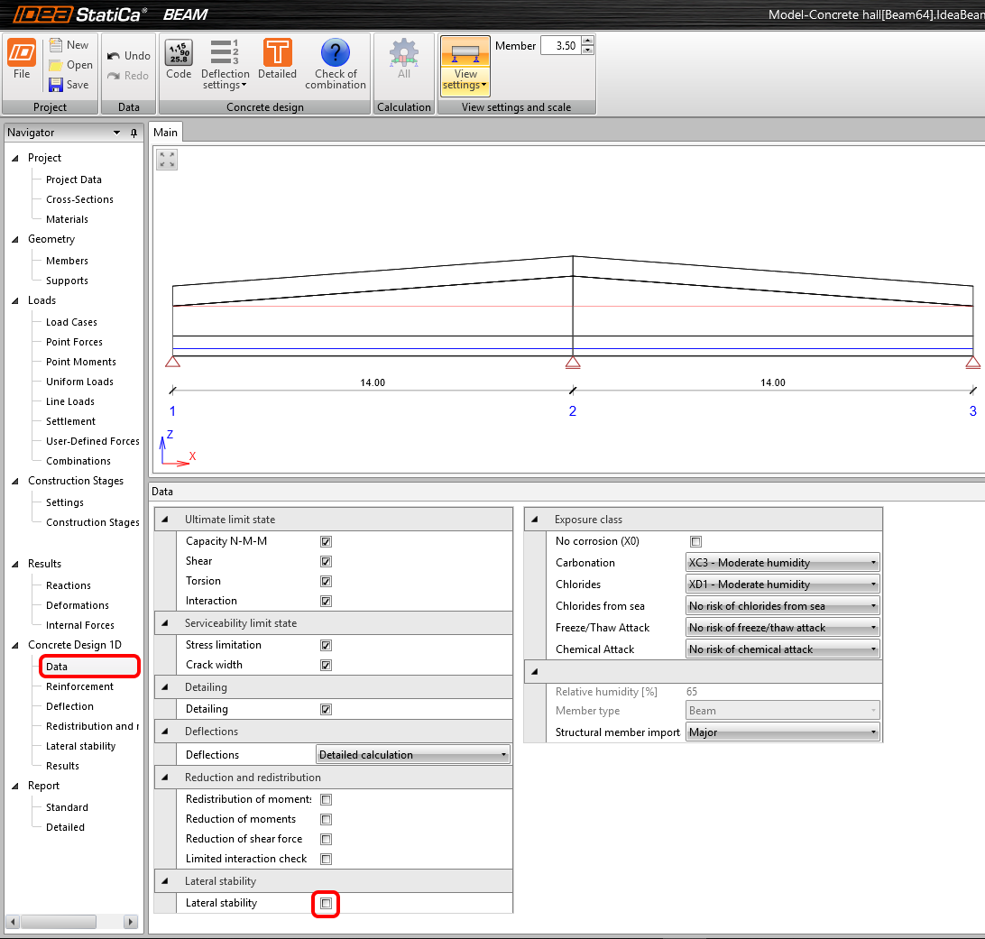
In Concrete Design 1D – Data in the left tree, you can find the settings of the checks that will be evaluated. All the checks are turned on by default. You unselect the Lateral stability evaluation, assuming that it is ensured.
Reinforcement
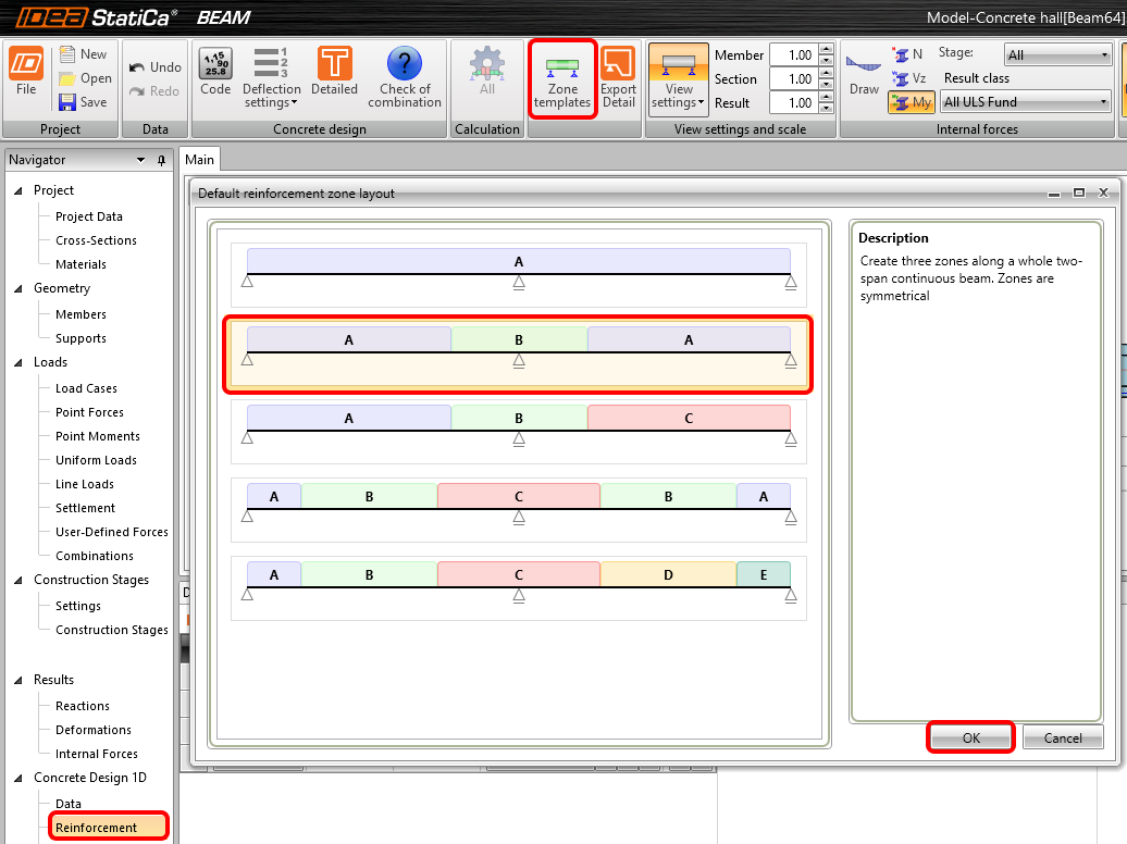
You will add some bars of Reinforcement now. Set the scheme of the reinforcement zones of the beam in the Zone templates (top ribbon). Select the second scheme which corresponds to a typical double-span beam.
Set the beginning and end of each of the Reinforcement zones (1) and the Check position (2) defining the sections where the concrete cross-section will be assessed.
You will reinforce the zone A–A (3) first and zone C–C (4) after that. The other two zones are symmetric and their reinforcement will be symmetric too. By clicking on the A–A in the figure, the reinforcement definition window opens.
You use the predefined template to reinforce zone A–A. Change only the Stirrups distance to 0.15 m.
Add the reinforcement of zone C–C by same procedure. Change the Stirrups distance to 0.2 m.
4 Calculation and Results
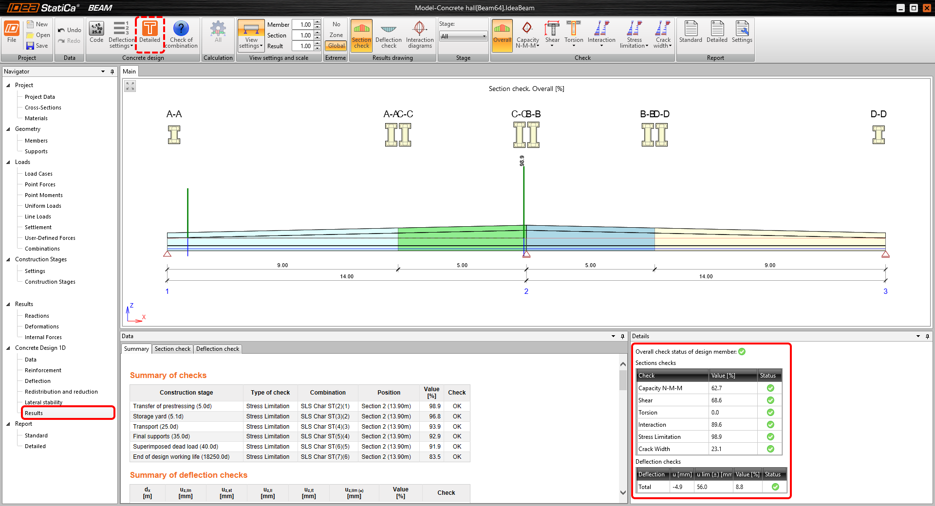
You run the calculation of the whole TDA analysis of the reinforced cross-sections by clicking on the Results in the left tree. After the calculation is finished, the overall check status appears with the maximum utilization. IDEA StatiCa Beam also provides in which stage and for which load combination the maximum utilization appears.
If you were interested in more detailed results in each section, you could open the RCS application by the Detailed button in the top ribbon.
5 Report
In the end, you can go through the Detailed report (in the left tree). IDEA StatiCa provides the possibility to adjust the protocol settings and also the final print into PDF or DOC file.


