Revit BIM link for connection design
1 How to activate the link
- Download and install (as administrator) the latest version of IDEA StatiCa
- Make sure that you are using the supported version of Revit
- Install Robot Structural Analysis
- Install Structural Analysis Toolkit for Autodesk Revit
After installation of both programs, run IDEA StatiCa and start with the item BIM.
In the BIM wizard, continue with the item Activate your BIM Link. During the process notification "Run as administrator" appears. Confirm with the button Yes.
Select your version of Revit and click the button Install. The process of integration will start.
2 How to use the link – Frame joint
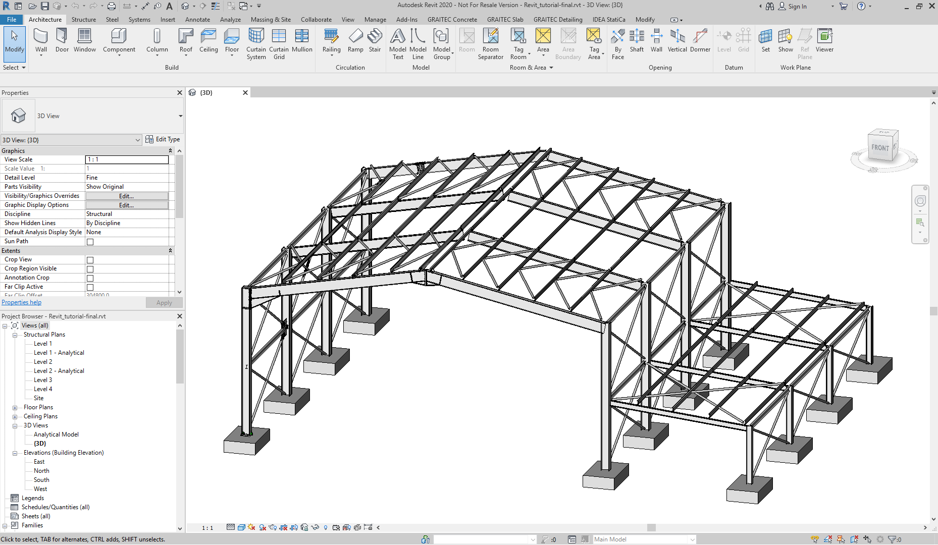
Open the attached project in Revit.
Revit is a kind of a unique tool for engineers because in Revit the geometrical and analytical model can be stored together with the analysis results. IDEA StatiCa Support team defined the geometrical model of the steel structure, defined analytical data (loads, load effects, combinations, etc.), imported it to the FEM analysis application and performed the analysis. In the next step, the analysis results are imported back to the Revit model. Let's check out if the results are available.
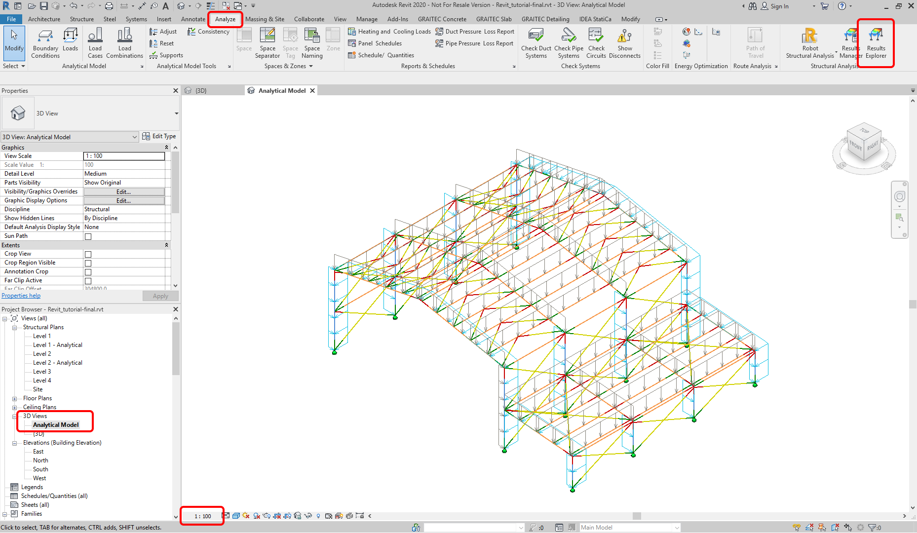
Double click on the Analytical Model view in the Project Browser tab. By this, the analytical model is shown. Also, the changing scale of the visualized items to 1:100 is handy. Choosing Results Explorer command in the Analyze tab is the next step.
The window Results for Analytical Model is shown. Choose the Analysis results and Com1 (which represents the Combination 1 defined in advance), then Moments My from the Results for Members group. Proceed with Apply. The FEM analysis results are available and can be explored.
Let's get back to the 3D model view and the left frame joint from the first frame must be found. For better visualization, the Hidden Line model view is recommended.
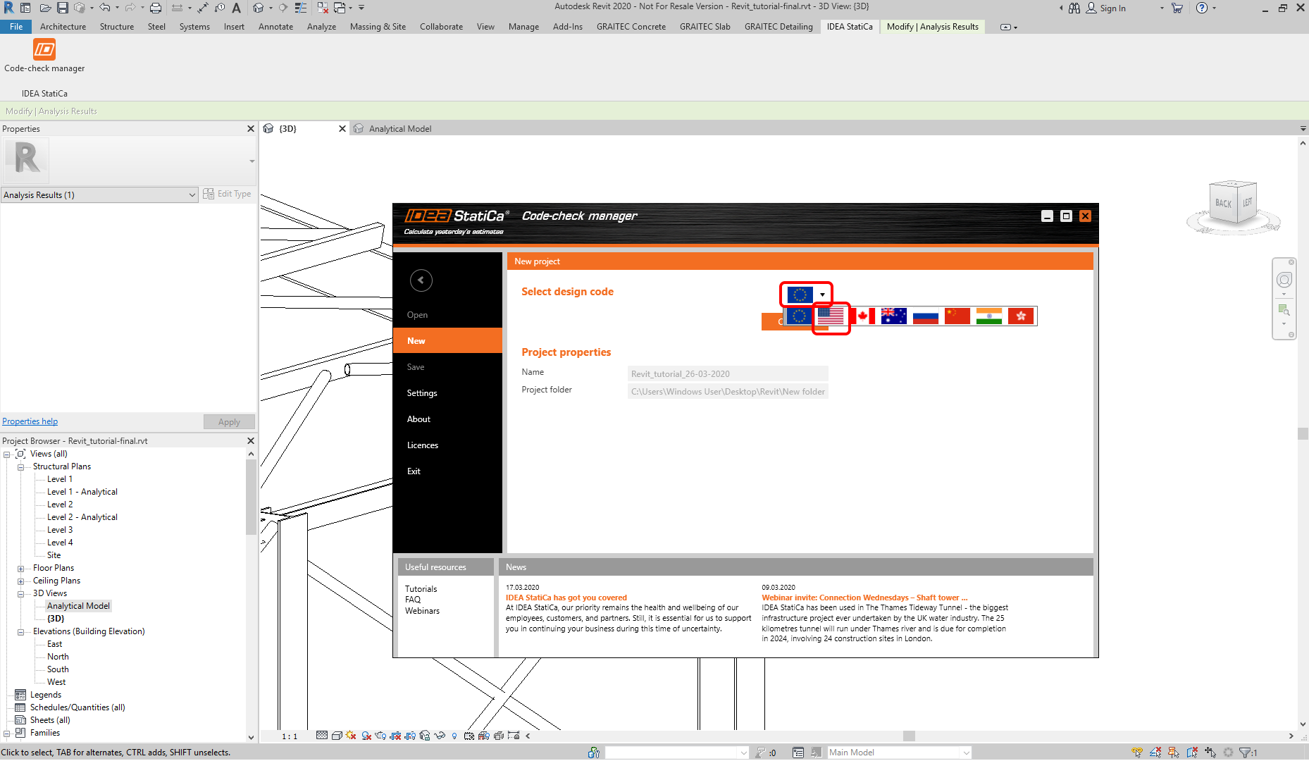
Let's proceed with starting the IDEA StatiCa Code-check manager from the IDEA StatiCa tab.
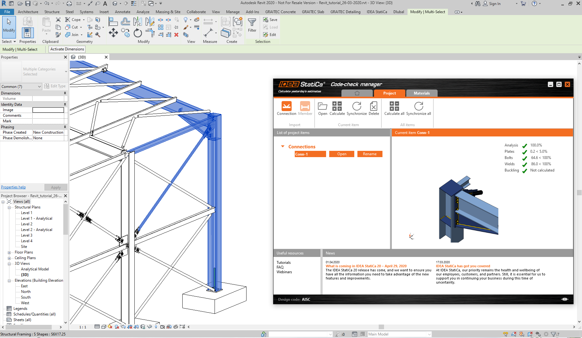
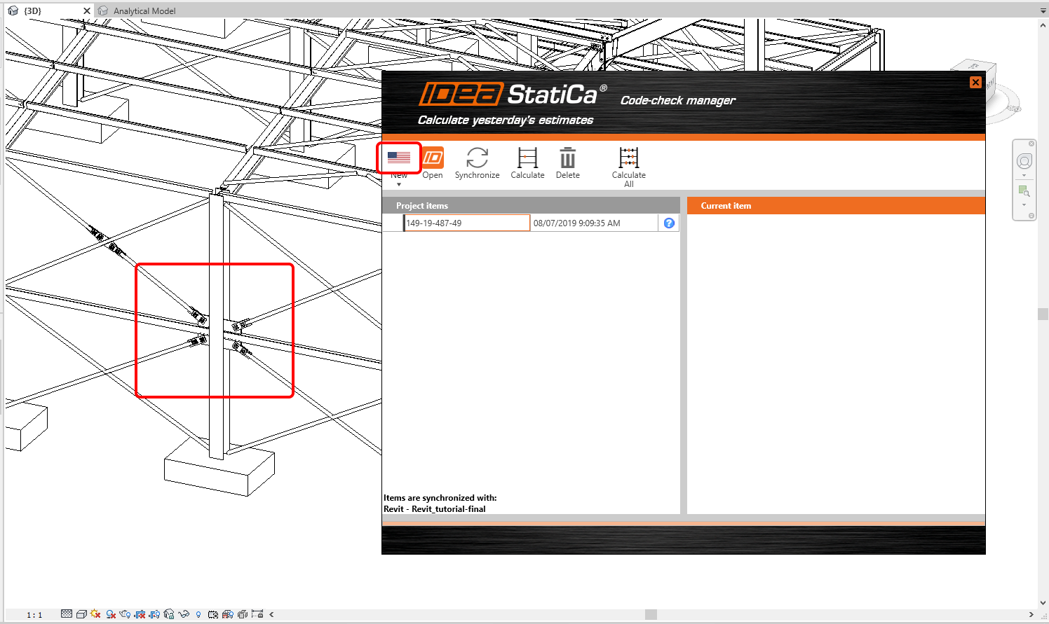
Code-check manager (CCM acronym further in the text) is a tool for exporting the connections, opening items created by the export, synchronizing changes in the model, etc. We will go through some of the commands further in this tutorial. Now let's use select the design code by clicking to picture of the EU flag or to the black arrow. Choose the AISC command. Confirm by Continue. By this step, the BIM import process will start.
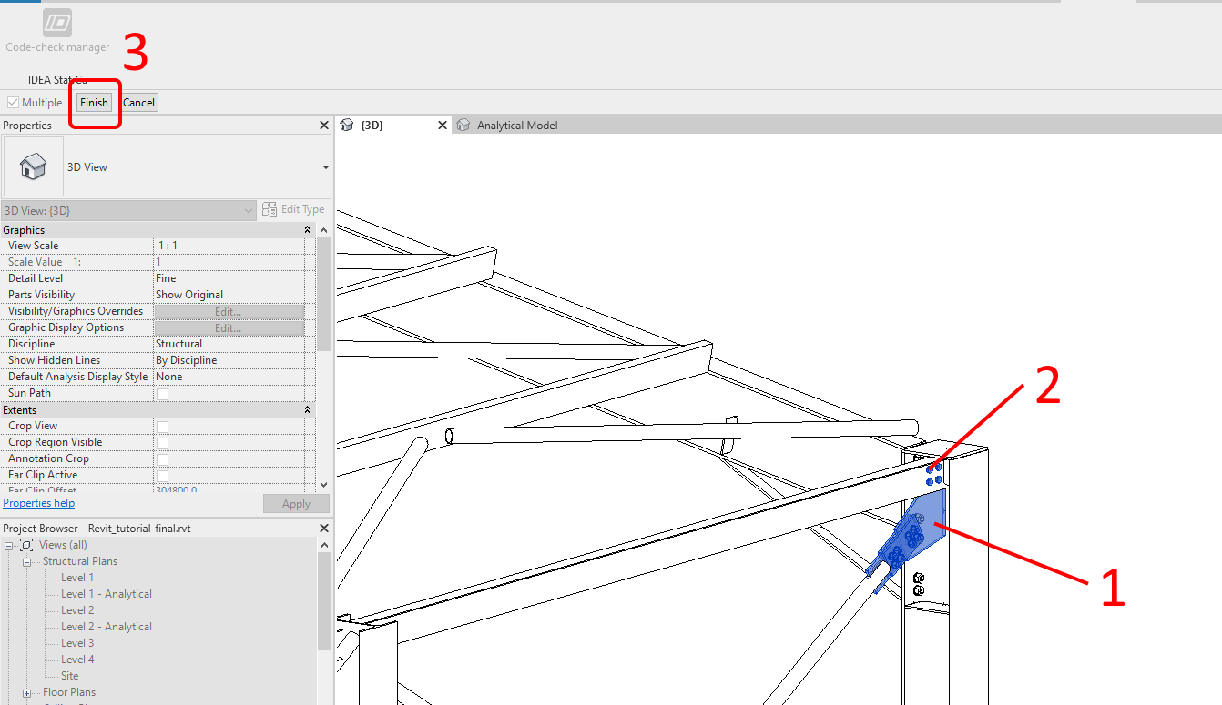
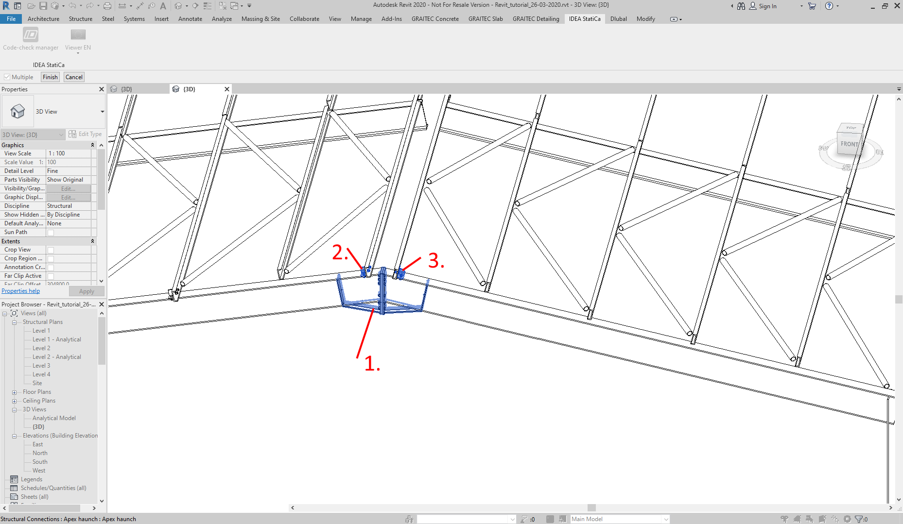
In the first step, choose the haunched frame connection shown in the picture below by the left mouse button click. Simply click on one of the connection items (joint was designed by the build-in macro).
In the second step (this step is optional), the other predefined connections can be assigned to the import. Choose two more parts of the whole frame joint, the connection of the bracing to the column (part 1) and the connection of the beam to the column (part 2). Confirm the selection by the Finish command (3).
After finishing the selection the CCM application performed the import and the item in the list of connections is provided. Select the Open command button.
3 Design – Frame joint
Automatic data transfer is finished and IDEA StatiCa Connection with the generated project is launched. All members and load effects were added automatically.
The properties of the Member 3 must be changed due to the fact, that Member 3 is connected with the shear connection. Move the Forces in to the Bolts.
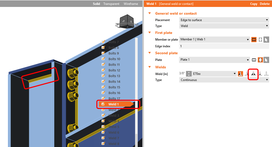
One weld definition must be changed. Let's rotate the model in a way that the weld under the column cap can be seen and click on it with the left mouse button. The right manufacturing operation will be chosen and it's properties shown in the right part of the window. Choose the double fillet weld.
4 Calculation and Check – Frame joint
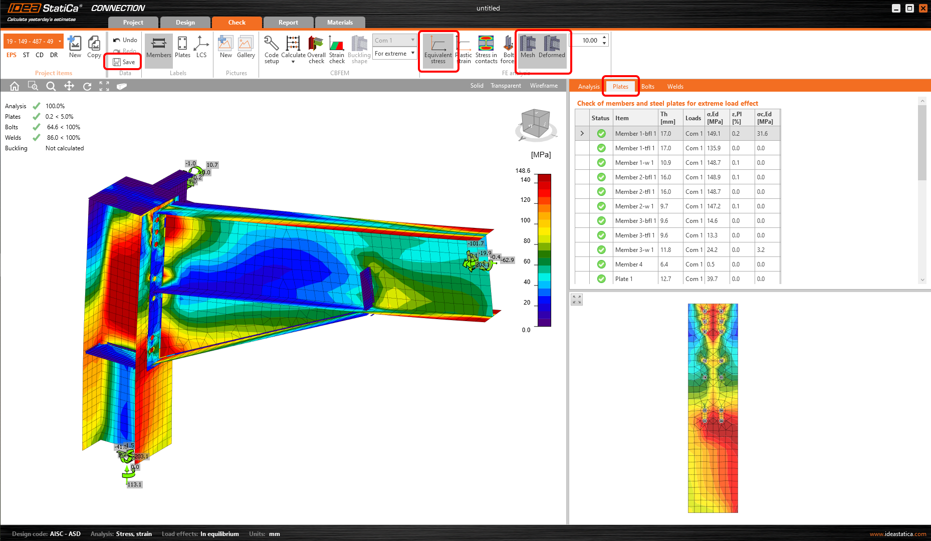
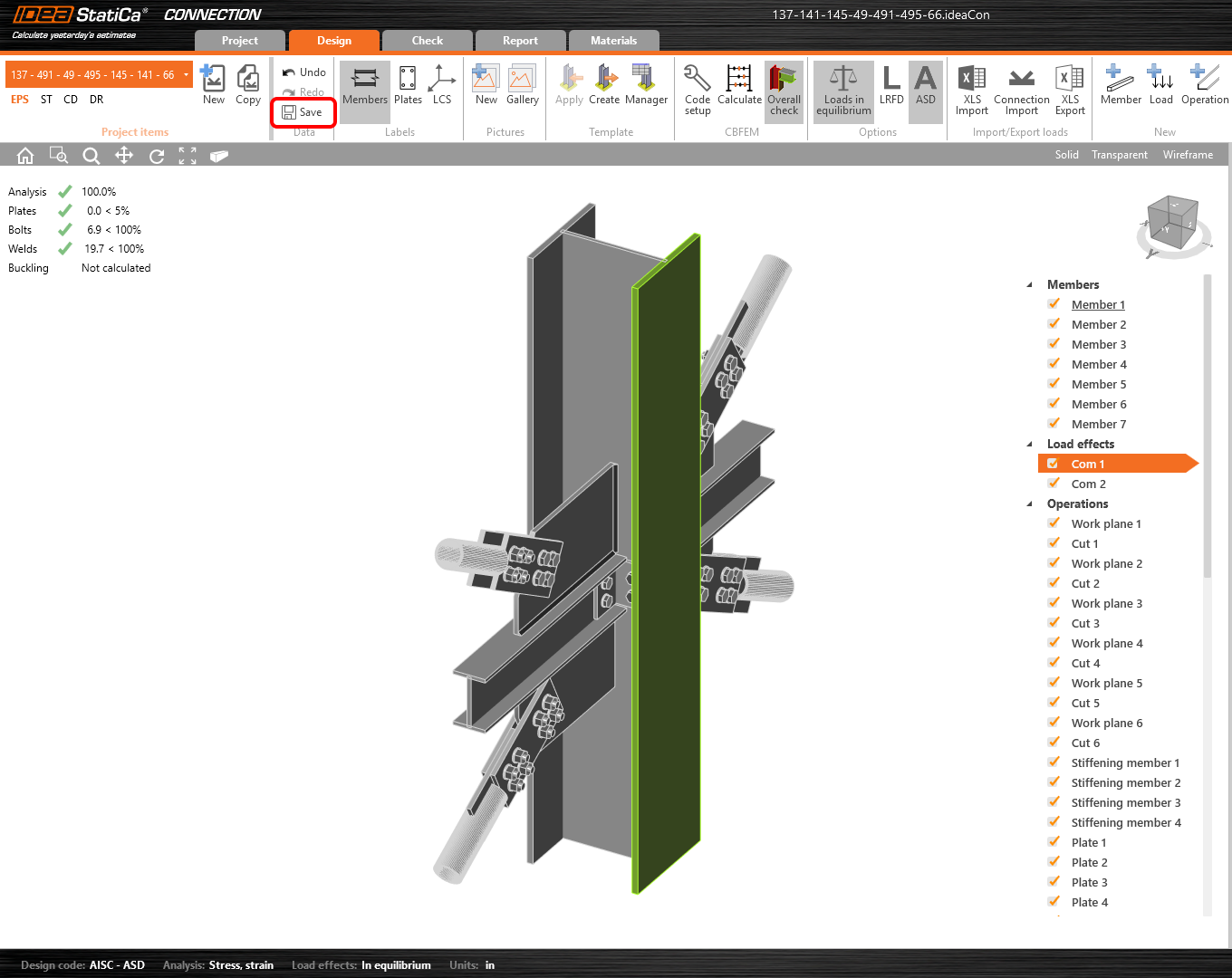
You can calculate the analysis right in the Design tab by the Calculate command. After the performed analysis let's change the tab to Check and set the Equivalent stress, Mesh, and Deformed model view. The results can be explored easily. If you are satisfied with the connection design now the data should be Saved. Now let's close the project window.
5 Report – Frame joint
In the Report tab, the protocol can be defined and printed out, if you need it. Let's close the Connection window now.
And we are back in the Revit with opened Code-check manager. Let's check out what can Code-check manager offer.
In the list of the Connections that can be found in the exported, designed and code-checked frame joint, information about the assessment is provided also.
6 Update – Frame joint
Let's take advantage of the Update function. Make changes in the Revit model connection and by one command update the IDEA StatiCa Connection model. Let's take a closer look at that.
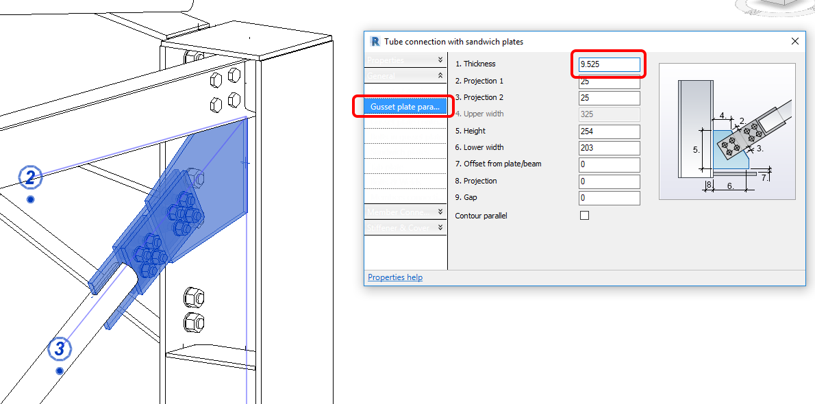
Let’s say we need to do changes in the Revit connection model. For example, the thickness of the gusset plate for the bracing member. Double click by the left mouse button on the connection entity to open the properties dialog.
In the connection properties dialog let's change Gusset plate parameters. The right value for Thickness will be 9.525 mm (3/8" in imperial units).
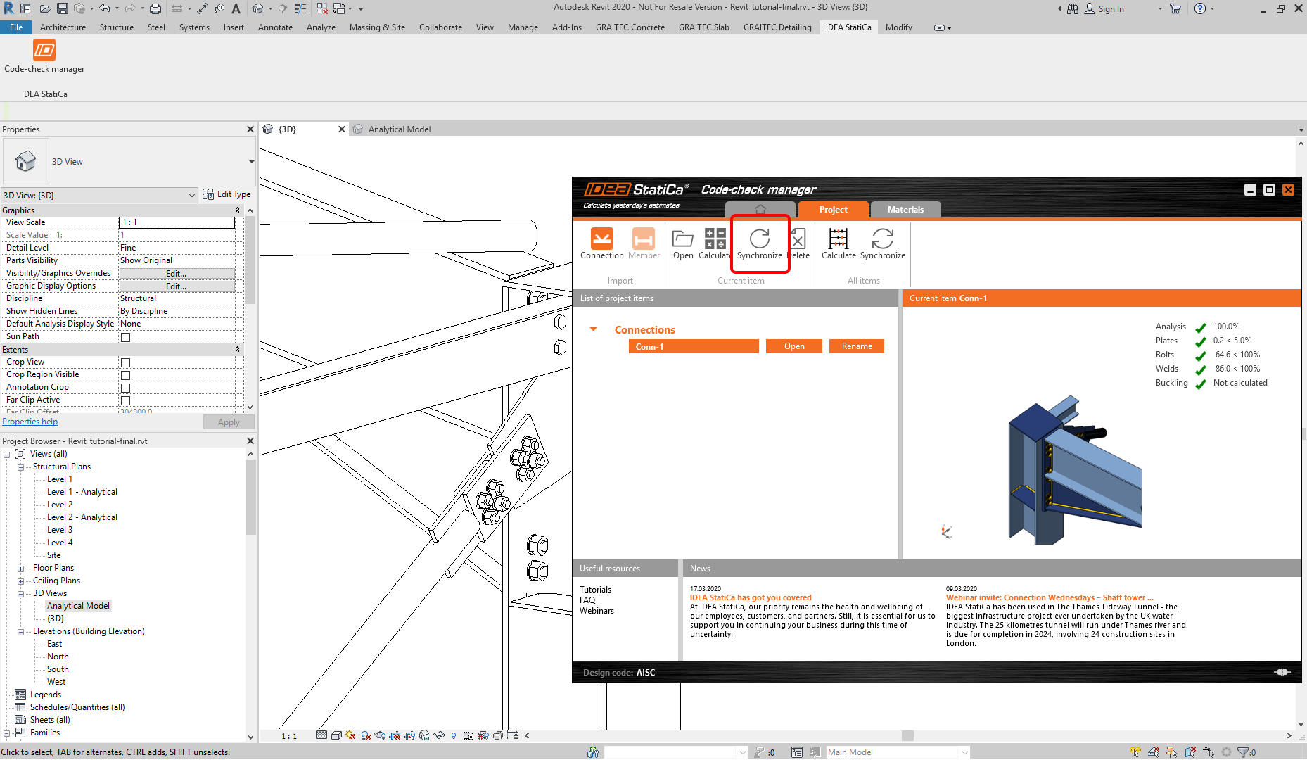
Now in the Code-check manager by the command Synchronize (Current item), the application will load the changes and update the Connection model.
In a while, the IDEA StatiCa Connection window will open with the updated frame joint. Let's check the thickness of the gusset plate. Hover mouse cursor over the gusset plate in the 3D scene, the gusset plate will be highlighted by the yellow color and brief information will appear in the left bottom corner of the 3D window. The change in the Revit model was brought to the IDEA StatiCa Connection model.
Before closing the project window we need to change the weld under the column cap to Double fillet weld again (Weld1) and Save the project. Then it can be closed.
7 How to use the link – Bracing
Now you already know how to use the Code-check manager. So let's perform import for another joint. Locate the X bracing joint to the column in the Revit model and export it by the New AISC command.
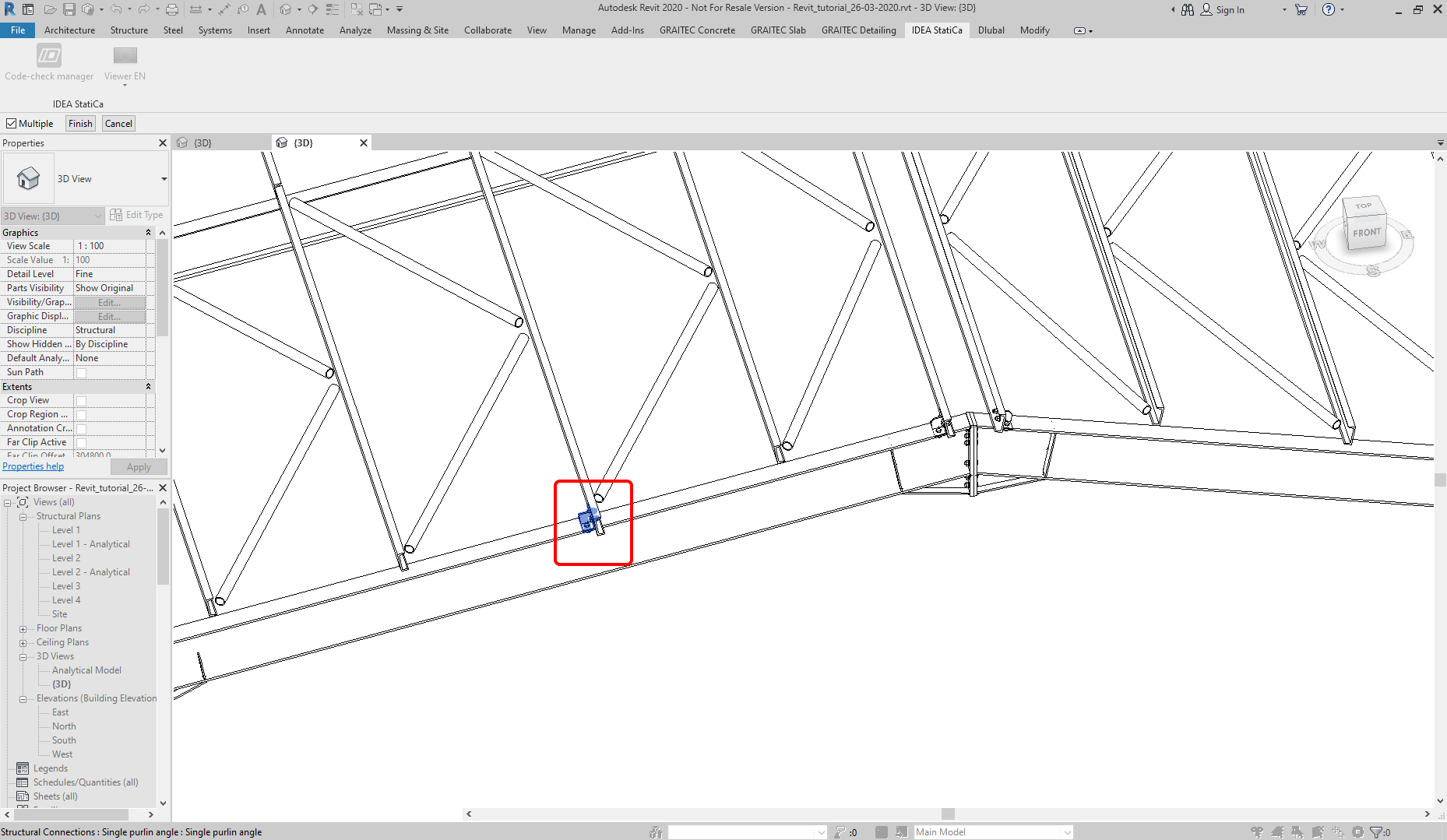
In the first step of the import procedure, we will choose the connection of one bracing member.
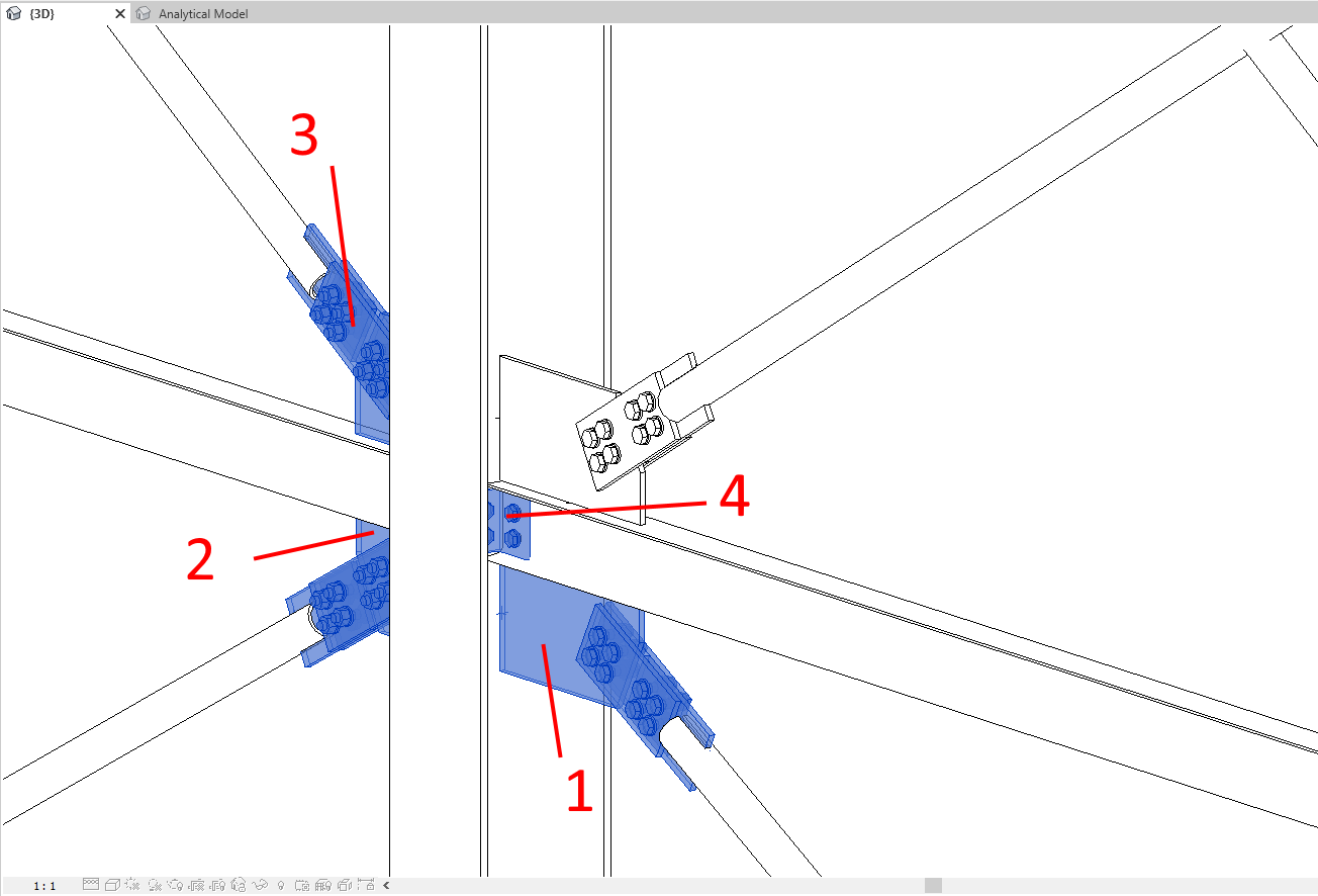
In the second (optional) step choose other connections that are present in the same node according to the picture below.
8 Calculation and Check – Bracing
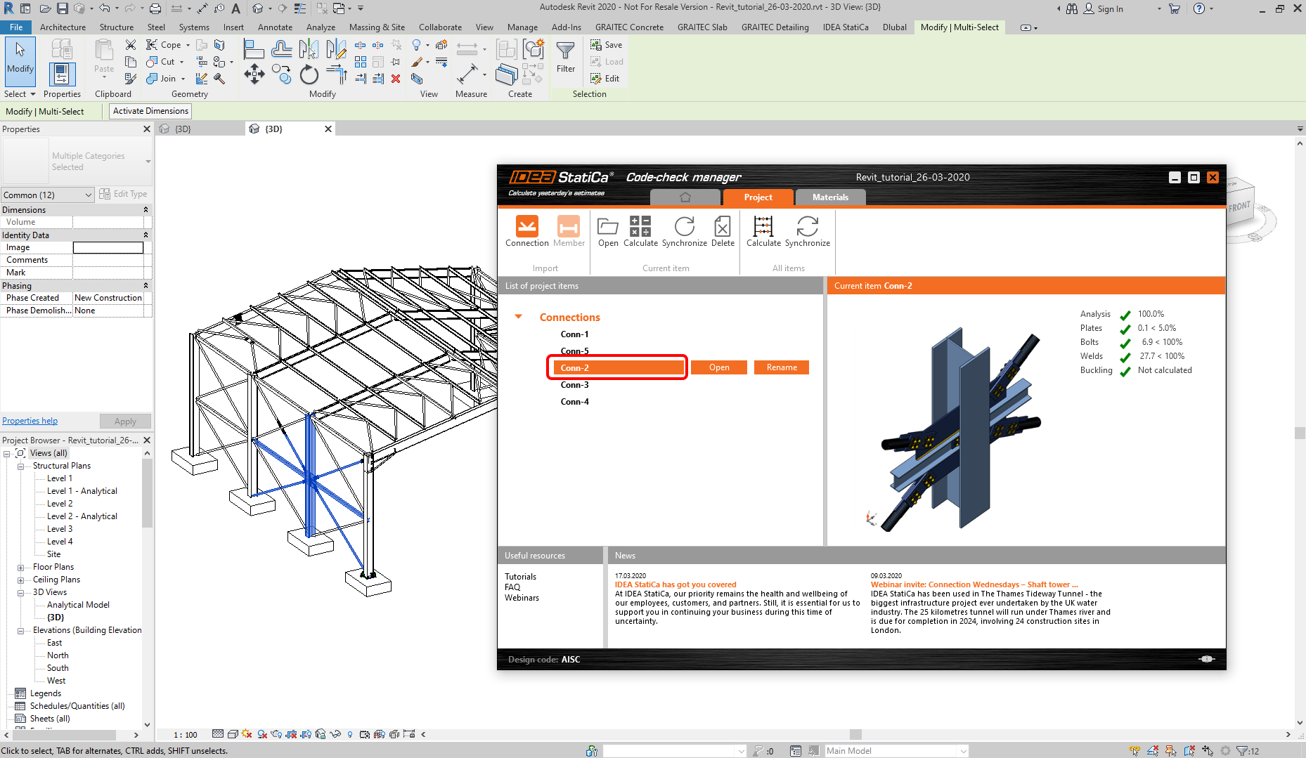
You already know how to open the project from Code-check manager, let's open the Conn 2. Now you can calculate the analysis right in the Design tab by the Calculate command.
After the performed analysis, don't forget to Save the data and close the window.
9 How to use the link – more connections
We are already familiar with the export process. So we will export the central apex joint. Just follow the order of the imported joints and Finish with the command.
The purlin which is near the apex joint will be also imported. This time only one selection has to be made.
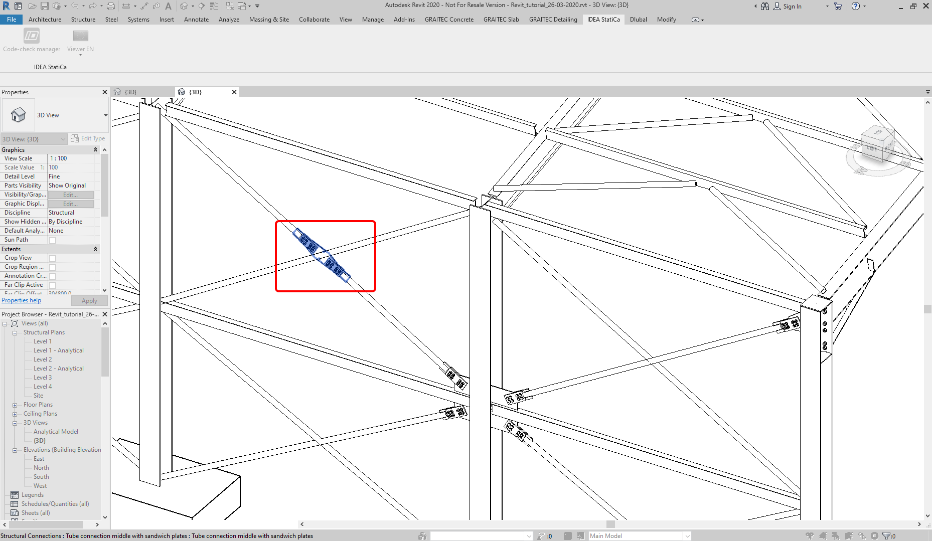
And the last import of this tutorial, the connection of the bracing tubes.
The Code-check manager contains five connections now. Each of them can be easily located in the 3D model by clicking on the row of the connection. The joint and its entities are highlighted in the 3D model by the blue color now.
10 Update of more connection items – Bracing
Let's take and advantage of the commands in the Code-check manager to update the model. If more changes in the project are needed and more exported joints are affected, you can use Synchronize (All items) command. This will save your time and update the connection data in one push.
Features for All items - Calculate and Synchronize are available only for the Steel Enhanced product owners.
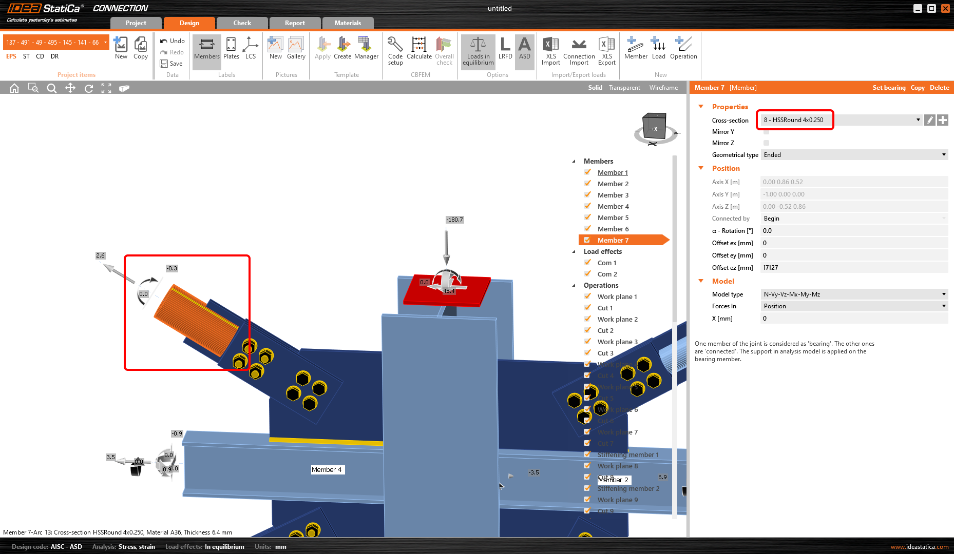
For example, you can change the cross-section of the bracing tube. The original one is HSS Round - HSS3X.250 cross-section.
For the sake of the example, change it to HSS4X.250. Don't forget to load the right cross-section from the Revit families.
While the Revit project file was changed, you should obtain a new set of FEM analysis results. The structure has been changed, the results are not valid now. We don't want to complicate this tutorial more so let's pretend that you have a new set of results (obtained from Robot Structural Analysis). You can proceed with the command Synchronize (All items).
After a while, the synchronization process will be done and you can open the Conn 2 or Conn 5 items and check out the cross-section of the bracing member.
We can check and adjust the design, recalculate the joint for code-check and save and close the project item. Then we can continue exporting and code-checking other joints.


