
Bridge segment modeling (EN)
The precondition for the design in Member application is designed and code-checked structure in the global FEM application.
1 New project
Open IDEA StatiCa and select the Member application.

Create a new project, type its name and select a folder where it will be saved. Then, choose the design code, starting material properties and the type of topology. Define the span of the analyzed member to 4 m. Finally, click on Create project and start modeling the structural detail.

The new project is generated and you can start with the design.

2 Analyzed members
The convenient way how to design structural detail in IDEA StatiCa Member is to follow the order of the tree of entities in the 3D window from the top to the bottom. You will start with Analyzed members.
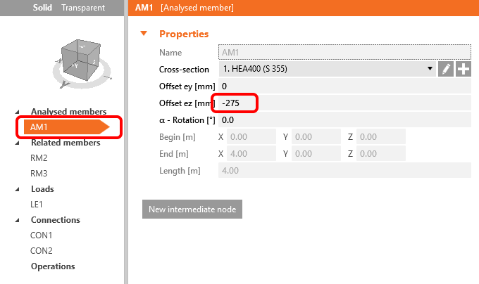
Set the Offset ez to -275 mm according to the global FEM model properties.
3 Related members
Related members generated by the wizard doesn't have the right properties and you will delete them all.

You must delete all the remaining related members. Your project looks like the one in the figure below now.

Now, it's time to add continuous related members in the right direction. In CON1, add Continuous Related member in the Y direction.

In added related member RM2, you will change the cross-section to the welded I section with the parameters according to the picture below.
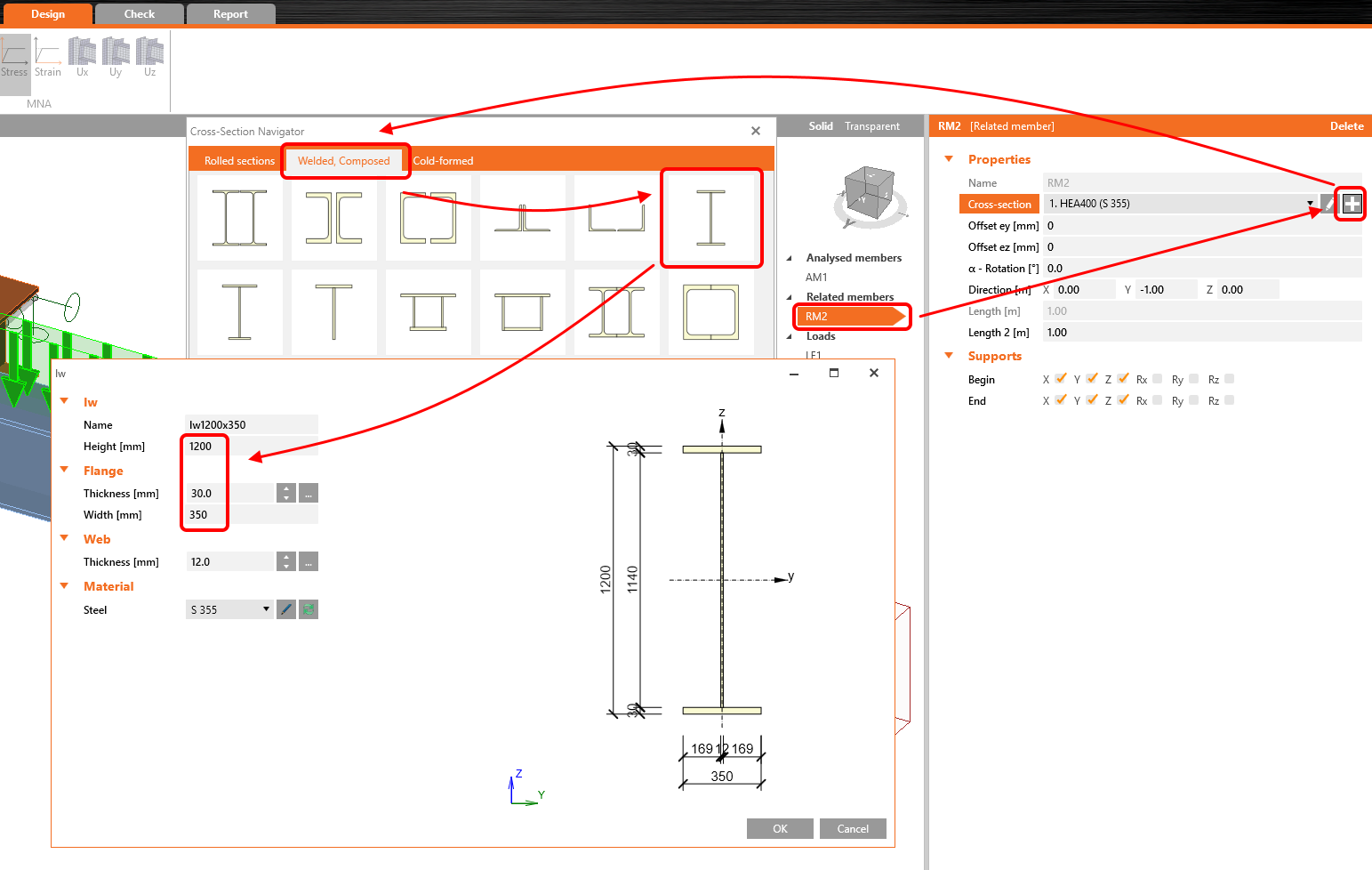
And finally, change the length properties and boundary conditions of RM2.

Now, it's time to add the second main beam by the second Continuous related member in the direction Y in properties of CON2.

Match the properties of the RM3 to the RM2.

4 Loads
This is a crucial part of the design in the Member application. It's not easy to load the model in the correct way. Our Support team definitely recommends the careful reading of the Theoretical background.
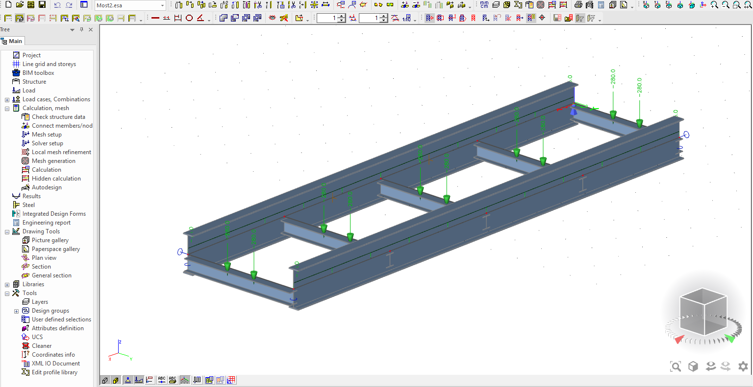
The engineer will gather all information about the loads and values of internal forces at the right section (cut) of the global structure from the global FEM model. It can look like in the figure below.

And you will manually load the Member model with gathered data. Let's use the LE1 load case and you will add Line loads and End forces.

5 Connections
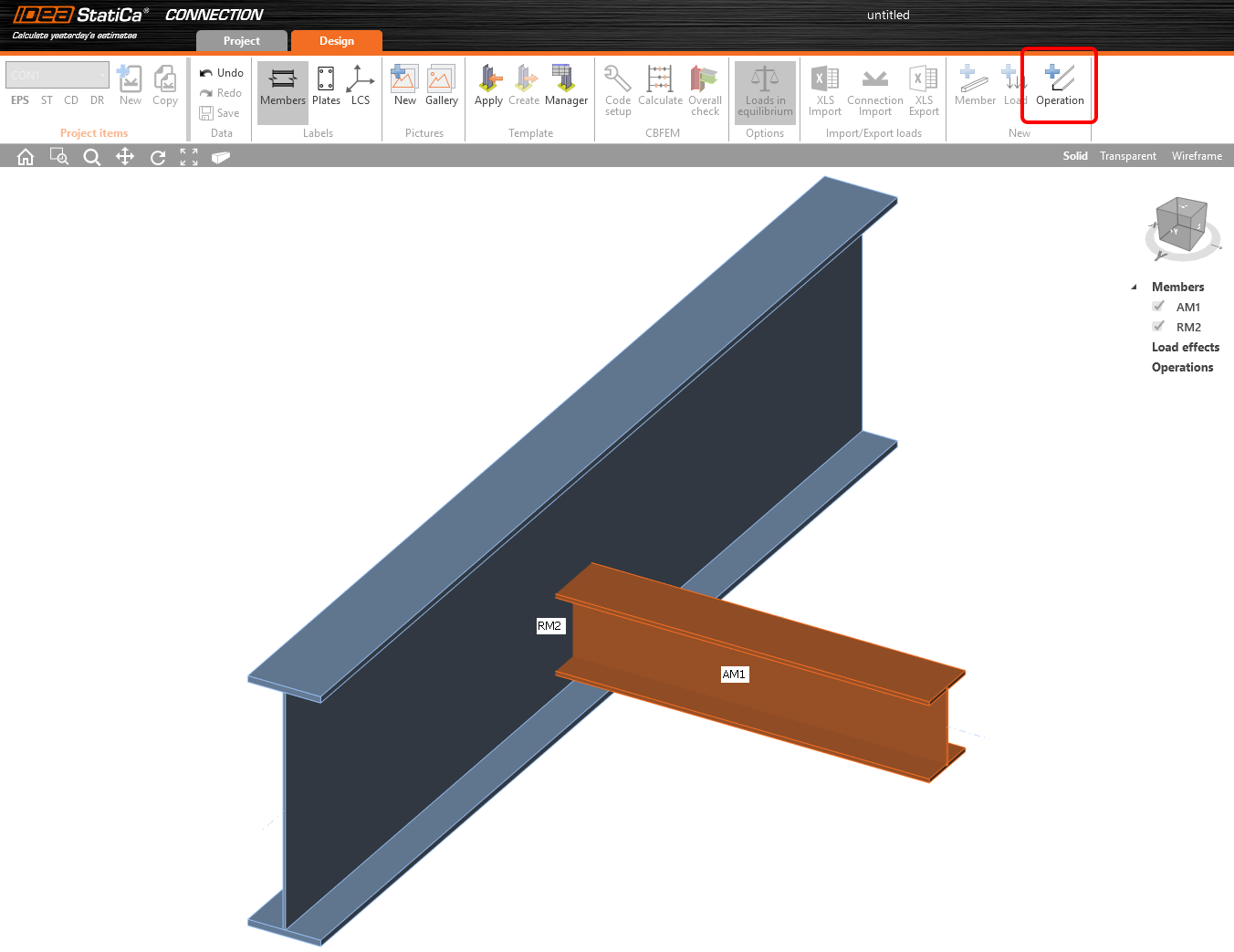
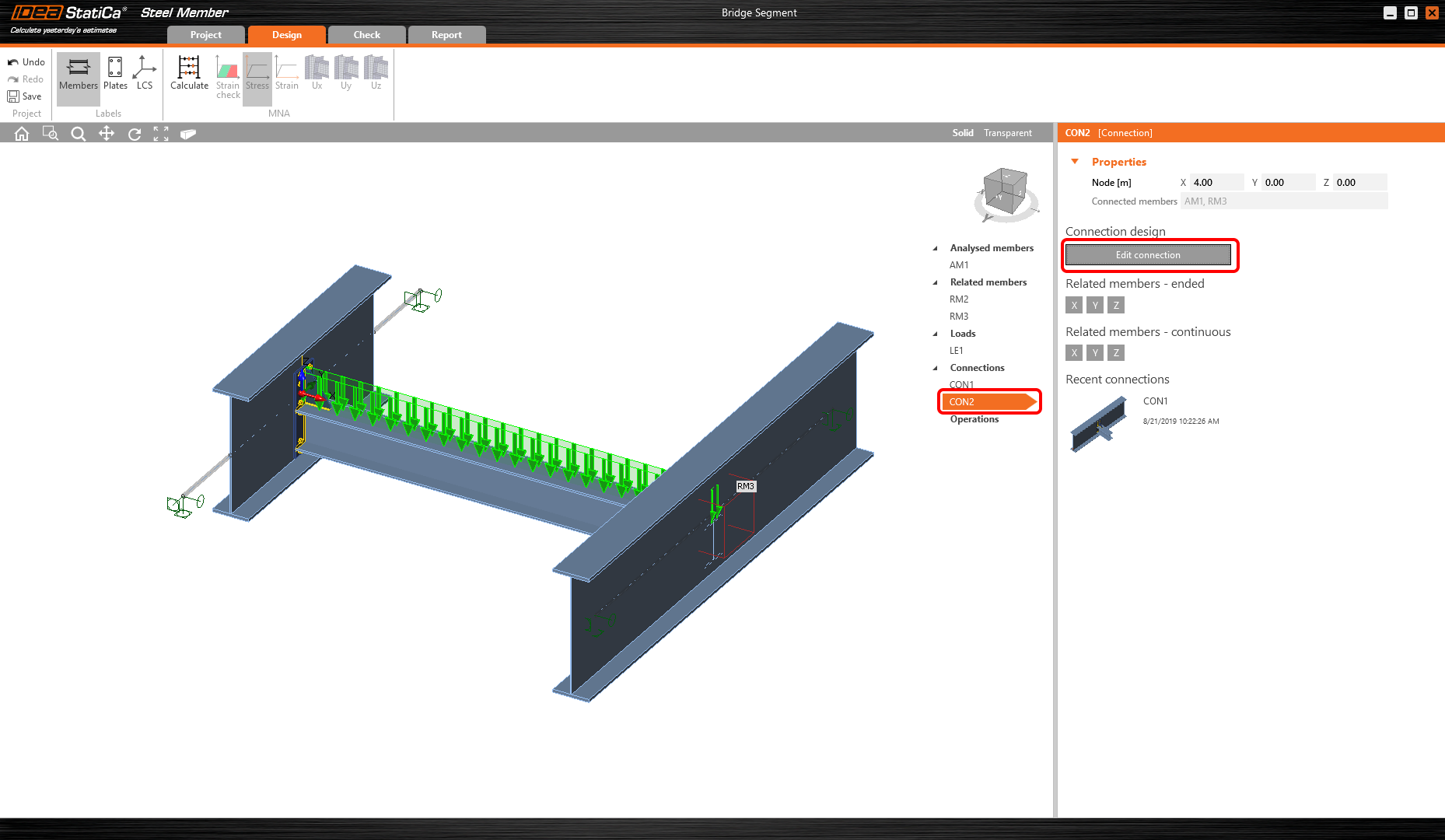
You can proceed to another item in the tree of entities. You will design the connections. Just choose the CON1 and Edit connection. IDEA StatiCa Connection window will appear in a few seconds.

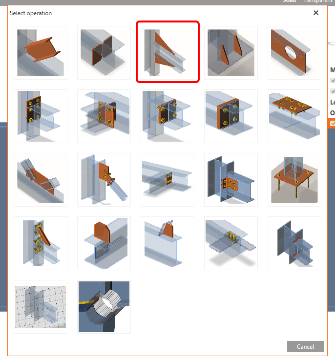
IDEA StatiCa recommends to drag the Connection window to the second screen and perform the design on two screens. It will speed up the design process. Now you will add manufacturing Operation.
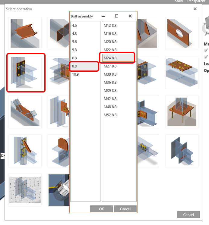
The application will ask for the definition of the bolt assembly. Choose M24 8.8.
Now, define the properties of the endplate.

The widener will be defined. Add a new manufacturing operation.
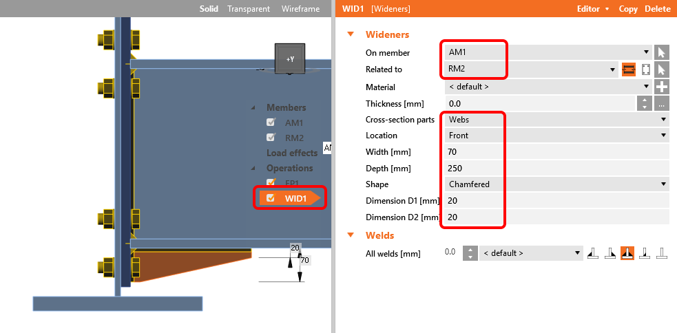
Define the properties of the first widener WID1.
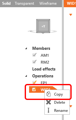
You can take advantage of the WID1 operation and create a Copy.
And change the properties of the WID2.

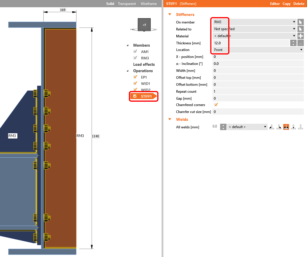
The last operation will be Stiffener.

And it's properties according to the figure below.

An important step at the end. You must Save the design. Once the design is saved, it will immediately appear in the Member model.

There is no need to close the Connection window. The Member application window is active and you can work simultaneously in both windows. You can Edit the connection in CON2 item.
The design of the CON2 will be the same as the design of the CON1, except the stiffener operation. Let's perform the design of endplate, both wideners according to pictures above.
Parameters of the STIFF1 operation will be set according to the figure below.
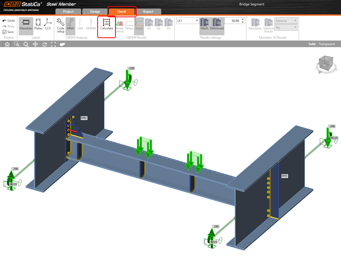
Don't forget to Save the design. After that, the Member model should look like in the figure below.
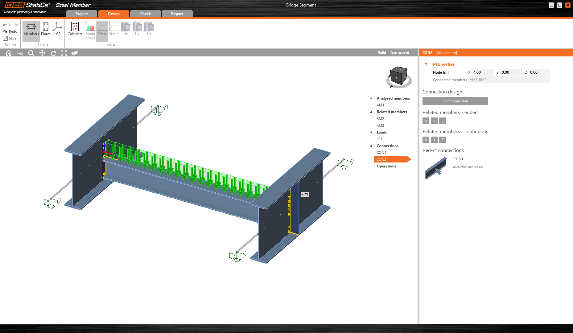
You designed the member model in the right way.
6 Check
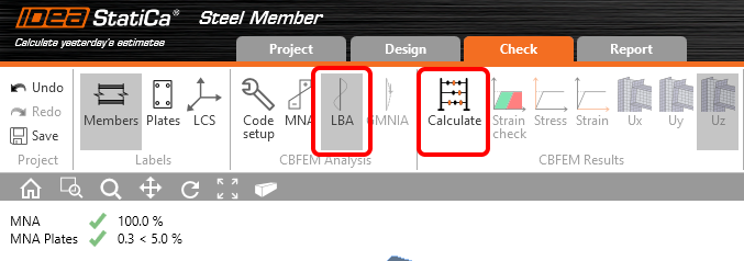
The check can be performed now. You can proceed to the Check tab. We have to perform the MNA analysis first, then LBA and at the last step, the GMNIA analysis can be performed. This order must be followed. Calculate the MNA.

The MNA results were delivered. You will check the results, turn on the Uz deformation view and check out the results.

Now, change the analysis type to LBA and choose the Calculate command.
LBA results were delivered. Check out the first buckling shape (it will be more visually clear with Uy deformed view set on). This buckling shape represents lateral-torsional buckling (LTB) stability loss.

The second buckling shape represents the local buckling of the high beam web.

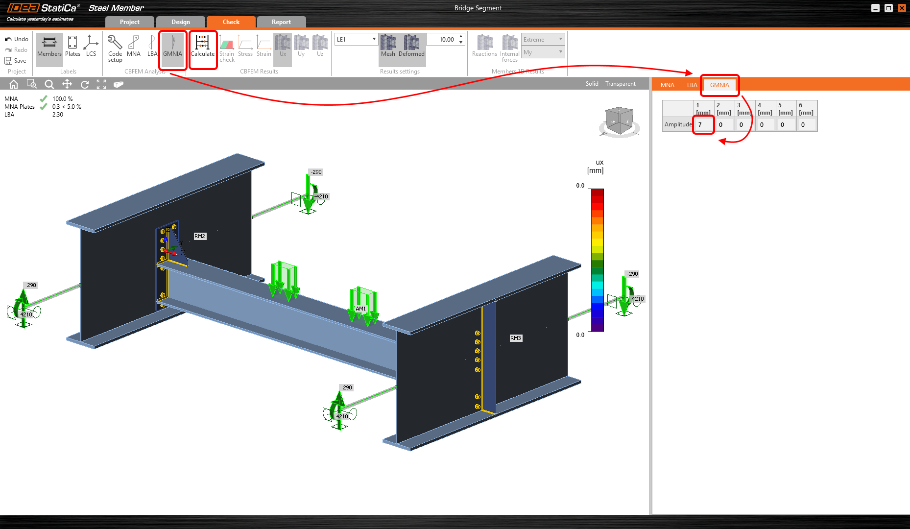
You must go through all provided buckling shapes and decide which one is the most critical one. IDEA StatiCa considers the first buckling shape the most critical one. According to EN 1993-1-1, the local imperfections are calculated for the analyzed member. IDEA StatiCa recommends studying the materials about the imperfections.
Analyzed member length is 4000 mm, L / 300 = 4000 / 300 = 13.33 mm. You want to analyze mainly lateral-torsional buckling failure mode so eccentricity amplitude is multiplied by k = 0.5.
The calculated value of imperfection is 7 mm for the first buckling shape. After setting the imperfections, you can start the analysis by the Calculate command.
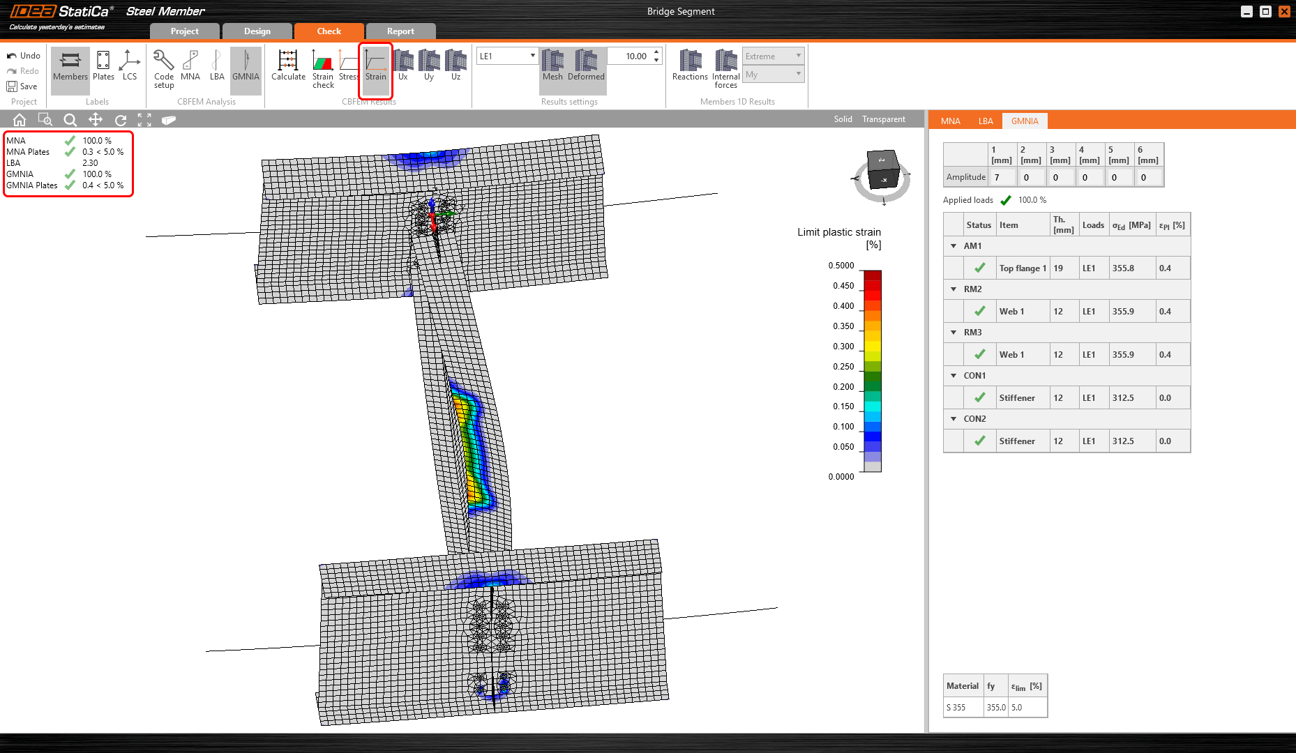
The GMNIA results are provided and you can check them out.
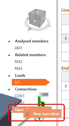
7 Operations
Several manufacturing operations such as openings, stiffeners, etc. can be applied to the analyzed member. You can add a New operation.
It's handy to add Transversal stiffeners to our analyzed member. Definition of the transversal stiffeners will increase the analyzed member resistance and you will check it.

Let's set the properties of the STIFF T1 according to the picture below.

You will add another stiffener and set its properties according to the picture below.

Now, you can start all analysis in the same way as the last time. You will check out the provided results with the influence of the stiffeners on the analyzed member.
8 Report
At last, go to the tab Report. IDEA StatiCa offers fully customizable report to print out or save in editable format.

We have designed and checked the diaphragm beam in IDEA StatiCa Member.