Methods for sectional capacity check
Two well-known methods can be used to check the ultimate limit state for 1D concrete members. The first one will give us the cross-sectional ultimate strength in the form of an interaction area or an interaction diagram (in the case of bending moment in one direction). Cross-sectional capacity can be determined as the ratio of acting internal forces to limit state forces. The second one is finding equilibrium in a cross-section, where we are looking for the actual behaviour of the loaded section, the use of materials in terms of stresses, and insight into the vulnerabilities of the section.
General design assumptions and calculation assumptions for Ultimate Limit State
- Strain ε in the reinforcement and concrete shall be assumed directly proportional to the distance from the neutral axis (plane sections remain plane).
- Interaction of the reinforcement and concrete is ensured by concrete and reinforcement interaction without slip (strain ε supports the strain in concrete adjacent fibers are the same).
- The tensile strength of concrete is neglected (all tensile stresses are transmitted by the reinforcement).
- Concrete compression stresses in the compression zone are calculated in relation to the strain calculated from stress-strain diagrams.
- Reinforcement stresses are calculated in relation to the strain from stress-strain diagrams.
- Compressive concrete strain with an ultimate strain limit εcu2 (Parabola-rectangle diagram for concrete under compression) and εcu3 (Bi-linear stress-strain relation), [2].
- The compressive strain of reinforcement is without limitation in the case of the horizontal plastic top branch, in the case of the inclined plastic top branch the strain is limited εud,[2].
- A limit state is considered when the state of at least one of the materials exceeds the ultimate limit strain (if εu is not limited, the compressed concrete is governing).
\[ \textsf{\textit{\footnotesize{\qquad Strain stress.}}}\]
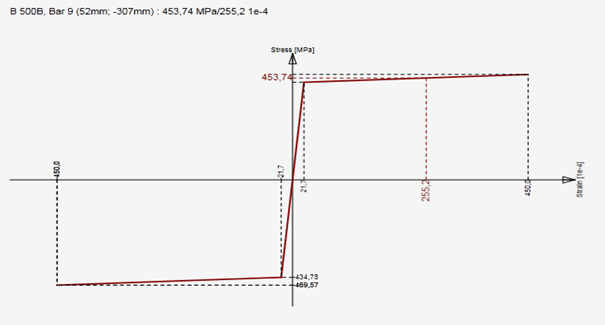
\[ \textsf{\textit{\footnotesize{\qquad Stress-strain design diagram for reinforcing steel with inclined top branch.}}}\]
Interaction diagram
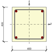
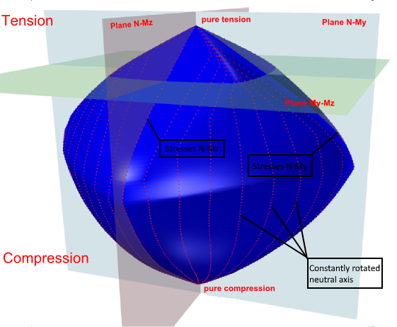
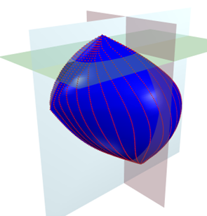
The first option is to check the cross-section by an interaction surface (or interaction diagram). An explanation is provided on a sample of the interaction surfaces for the reinforced square section from the example in the figure below. On the interaction surface are located points defining the ultimate limit state of the examined cross-section. The interaction surface is drawn from the points (N, My, Mz), which are determined by stress integration in the cross-section, which has achieved ultimate limit strain in one of the materials. For a 3D interaction, the surface can be derived from a 2D interaction diagram, which is a closed curve, which corresponds to the stress of a constantly rotated neutral axis.
\[ \textsf{\textit{\footnotesize{\qquad Symmetrical reinforced cross-section.}}}\]
\[ \textsf{\textit{\footnotesize{\qquad Interaction surface shows failure conditions for all load cases of normal force and bending moments.}}}\]
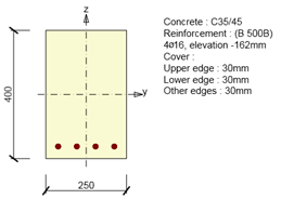
For the case of a symmetrical cross-section about the y-axis, the interaction diagram is symmetrical around the plane N-My. Identically, for the case of a symmetrical cross-section about the z-axis, the interaction diagram is symmetrical around plane N-Mz. The one-sided reinforced section introduces a flattened shape of the interaction diagram
\[ \textsf{\textit{\footnotesize{\qquad Single symmetrical reinforced cross-section.}}}\]
\[ \textsf{\textit{\footnotesize{\qquad Interaction surface for cross-section with single symmetric reinforcement.}}}\]
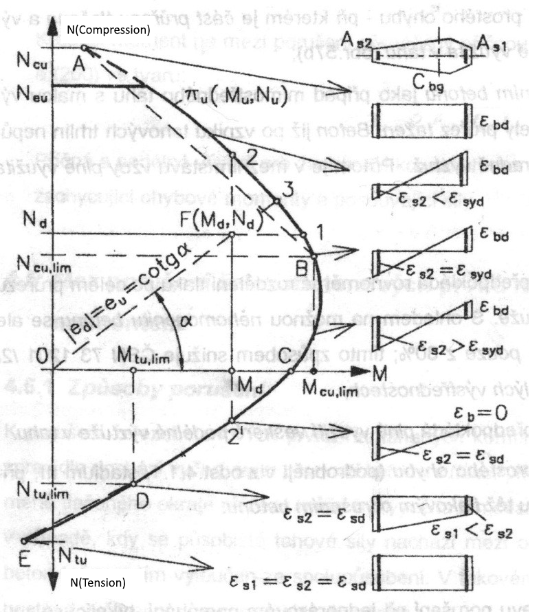
The points defining the ultimate limit state are received from stress integration. The figure below displays strain at the ultimate limit state.
Strain distributions at the ultimate limit state (taken from [2]).
The interaction diagram shows cross-section failure under normal force and bending moments. [1]
Respecting the 2D diagram problem (closed curve laying on interaction surface) we can find out the strain plane is passing through the neutral axis and critical point [y, z, ε], which is considered as critical point R. Point [y, z] defines a point in cross-section with the value of strain ε at the ultimate limit state. The neutral axis inclination is constant for all points of the 2D diagram.
In case the compressive stress in concrete is critical for design, point R is matching the farthest compressed concrete fiber or to limiting point C. However, this can be applied only if that section is made from one type of concrete - not such as a mixed cross-section.
In the case the tensile stress in reinforcement is critical for design (strain εud is exceeded at the ultimate limit state for one or more bars), there must be fulfilled condition that for the given strain plane the value εud is not exceeded at any other bar.
\[ \textsf{\textit{\footnotesize{\qquad Optimal use of cross-section material.}}}\]
\[ \textsf{\textit{\footnotesize{\qquad Characteristic strain plane positions calculated for purpose of interaction diagram.}}}\]
The picture above shows that the diagram can be divided into two parts: the part where the failure is caused by tensile force and the part which fails by a compressive force. The limit points correspond to the case above, where the extreme inclination of the strain plane also can be seen. When drawing an interaction diagram the plane strain inclination of a cross-section is changing in this interval, while we search for the point R (see above). Based on that defined plane we perform the integration to get the stress at the ultimate limit state.
Cross-section subjected to axial force and bending moment check
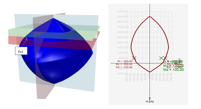
The check of a cross-section subjected to axial force and bending moment relies in proving that the checked stresses (combination Nd, Myd, Mzd) are located inside or on the surface interaction area. Different methods can do this. The following example demonstrates the check of a rectangular cross-section subjected to forces Nd = -500 kN, Myd = 120 kNm, Mzd = 100 kNm.
Method NuMuMu
To define the resistance of a cross-section we assume proportional changes in all of the internal force components (the eccentricity of the normal force remains constant) until the interactive surface has been developed. The change of involved internal forces can be interpreted as moving along a line connecting the start coordinate system (0,0,0) and the point defined by the internal forces (NEd, MEd,y, MEd,z). The two intersections of this line with the interaction surface, which can be found, represent two sets of forces at the ultimate limit state. At each intersection, the program determines three forces at the limit state: the design axial force resistance NRd and the corresponding design moments of resistance MRdy, MRdz.
Method NuMM
To define the resistance of cross-section we assume constant normal force (which is equal to the acting design normal force) and proportional changes in bending moments until the interactive surface has been developed. The change of involved internal forces can be interpreted as moving in a horizontal plane along the line connecting the point (NEd,0,0) and the point defined by the acting internal forces (NEd, MEd,y, MEd,z). The two intersections of this line with the interaction surface, which can be found, represents two sets of forces at the ultimate limit state. At each intersection the program determines three forces at the limit state: the design resisting moments MRdy, MRdz and (corresponding) acting design normal force NEd.
Method NMuMu
To define the resistance of the cross-section we assume a constant normal force (which is equal to the acting design normal force) and proportional changes in bending moments until the interactive surface has been developed. The change of the involved internal forces can be interpreted as moving in a horizontal plane along the line connecting the point (NEd,0,0) and the point defined by the acting internal forces (NEd, MEd,y, MEd,z). The two intersections of this line with the interaction surface, which can be found, represent two sets of forces at the ultimate limit state. At each intersection, the program determines three forces at the limit state: the design resisting moments MRdy, MRdz, and (corresponding) acting design normal force NEd.
Finding the section response
Another possibility to check the cross-section is by finding the cross-section response (i.e. Strain and stress distribution from acting internal forces). This method is also known as the method of limit deformation. The level of acting stresses in each fiber (in the case of plane bending in each layer) in each reinforced bar is calculated depending on the strain of the Stress-strain diagram of the material.
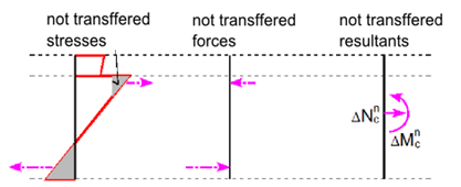
Finding the cross-section response is calculated using the numerical method specified in [6]. The principle consists of the gradual load increment of the section by the unbalanced components of not-transferred forces. Those are obtained by integrating the stress over the section using Stress-strain diagrams. If the stress value can be found for the strain in the Stress-strain diagram, see Figure below (a), the calculated stress is correct assuming linear elastic material. In cases (b) and(c), the stress for a linear calculation reaches unrealistic values, and part (b) or entire value (c) cannot be transmitted by the material. Integrating not-transferred stresses we get not-transferred internal forces, and their resultants should be added to the internal forces of variable loads.
Not-transferred stresses in Stress-strain diagrams. [4]
Not-transferred inner forces. [4]
This calculation method requires the use of numerical methods for integrating the stress over the cross-section area and for nonlinear analysis of equilibrium equations in the section. Iteration is terminated at the time when the convergence criteria are met.
\[\frac{{{F_e} - {F_i}}}{{{F_e}}} \le max\left\{ {e,d} \right\}\]
where
Fe is section load,
Fi is section response (internal forces calculated on the base of the strain plane).
If a is the approximate (approximated) value and b is the exact (true) value, then absolute deviation is given by the following equation.
\[e = \left| {b - a} \right|\]
Relative deviation is given by the following formula:
\[d = \left| {\frac{{b - a}}{b}} \right|\]
In most programs, you can set these convergence criteria (default values are 1% as relative error, 100 N, 100 Nm as the absolute error of normal force and moments).
So if we have the input of N = 0 kN, My = 100 kNm, Mz = 0 kNm and integrated forces after iteration N = - 0.07 kN, My = 100.5 kNm, Mz = 0.02 kNm, the evaluation will be as follows. With respecting the N and Mz being equal to 0, a comparison with absolute deviation can be done:
The value of normal force 100N> | 70 | N
The value of the bending moment Mz 100Nm> | 20 | Nm
The value of the bending moment My
\[d = \left| {\frac{{b - a}}{b}} \right| = \frac{{100 - 100,5}}{{100}} = 0,005\; < 0,01\]
Cross-section check by the response
In the case of finding a balance in the cross-section, plane strain is known. From the plane strain we can calculate strain anywhere in the section, then the stress or inner forces in reinforcement bars, cross-section or its parts using Stress-strain diagrams of the materials. The calculated stress and strain values we compare with the limit strain value from the stress-strain diagrams of the used materials.
The advantage of this method is that we get a complete image of the stress and strain values in the section of the internal forces acting on the cross-section.

