
Autodesk Revit BIM link for connection design (AISC)
링크를 활성화하는 방법
- 최신 버전의 IDEA StatiCa를 다운로드하여 설치하십시오
- FEA 솔루션의 지원 버전을 사용하고 있는지 확인하십시오
IDEA StatiCa는 설치 중에 FEA 소프트웨어에 BIM 링크를 통합합니다. IDEA StatiCa를 실행하고 BIM 링크를 열어 상태를 확인하고 필요에 따라 추가 BIM 링크를 통합할 수 있습니다. 일부 FEA 소프트웨어는 IDEA StatiCa에 대한 BIM 링크를 완전히 활성화하기 위해 추가 단계가 필요할 수 있습니다.

"이 앱이 장치를 변경할 수 있도록 허용하시겠습니까?"라는 알림이 나타날 수 있으며, 그럴 경우 예 버튼으로 확인하십시오.
설치를 클릭하면 선택한 소프트웨어에 대한 BIM 링크가 통합됩니다. 화면에는 다른 BIM 링크의 상태도 표시됩니다.

How to use the link
Autodesk Revit (Revit) has a feature that is not currently found in other BIM applications in that it can also host results from a suitable finite element analysis solution. To that end we have created such a model for you to use with this tutorial using Revit 2023. The results have been obtained using Robot Structural Analysis 2023. Revit 2023 introduces a new approach to analytical modeling and has moved away from automation to a more engineering centric approach.
Open the model in Revit - note this tutorial requires version 2023 or higher.
There are two Analytical 3D views that have been created to verify the loads and results.
Here are the loads that have been defined (partly in Revit and more in Robot):
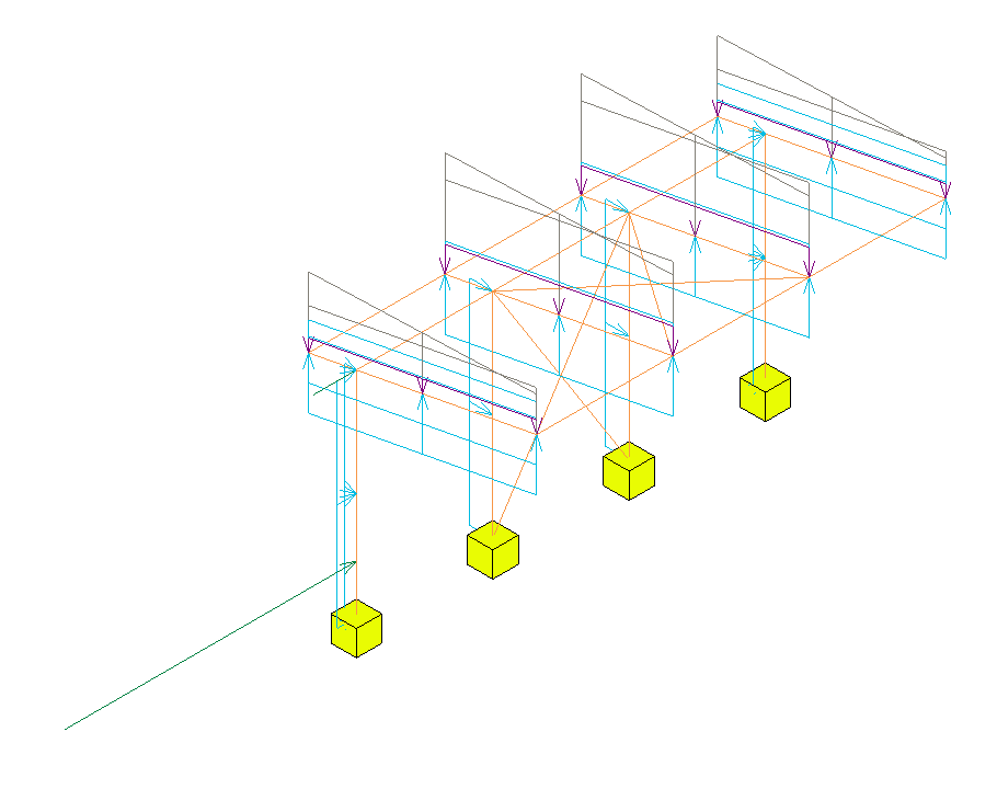
The code combinations were defined in Robot as this was much easier to do and you could argue that this is the correct place to define them. Another observation here is that the model in Revit is fairly code/country agnostic until this stage - as the loads could be applied to any national annex to generate a 'local' solution.
Although the view is 'Locked' the results still need to be loaded. To do this go to the Analyze tab and select Results Explorer.

In the next window choose a suitable ULS load case combination, My for example and finally Apply.

If you expand the view (remembering to unlock it first) you will also see the legend. The text size is affected by the overall view scale so this can also be adjusted.
The results show the My values for a ULS load case combination that was defined in Robot.
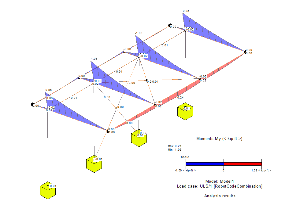
Different results can be visualized using the Results Explorer functionality from the Analyze tab.
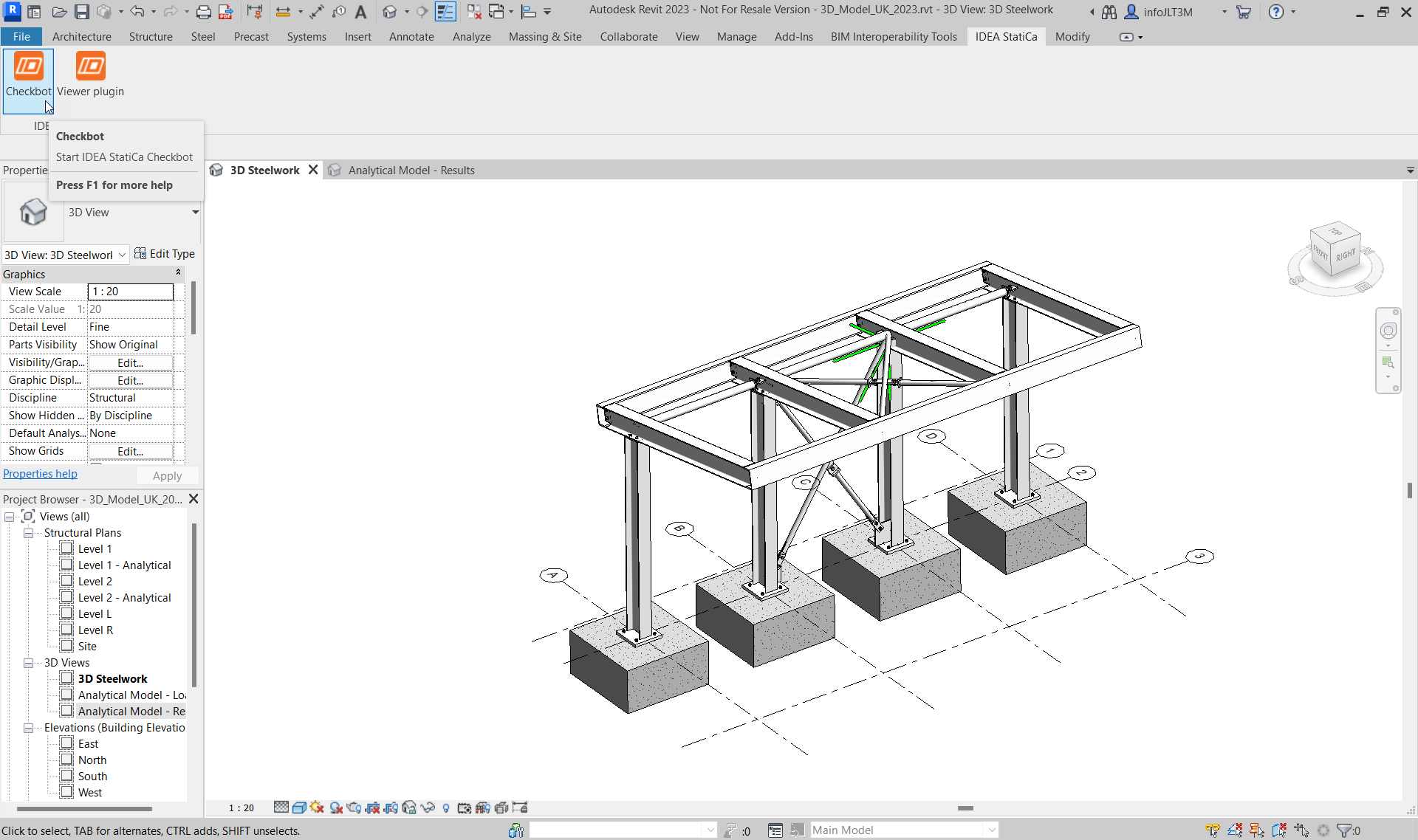
Return back to the 3D Steelwork view. The steel connections shown have been modeled from within Revit. They can only be seen if the Detail Level is set to Fine.
The BIM link should be automatically integrated. You can find it in the top ribbon under IDEA StatiCa -> Checkbot. This will open the Checkbot application.
Select the New option with project type Steel and design code USA/ASD (AISC 360-16). Then select Create project.
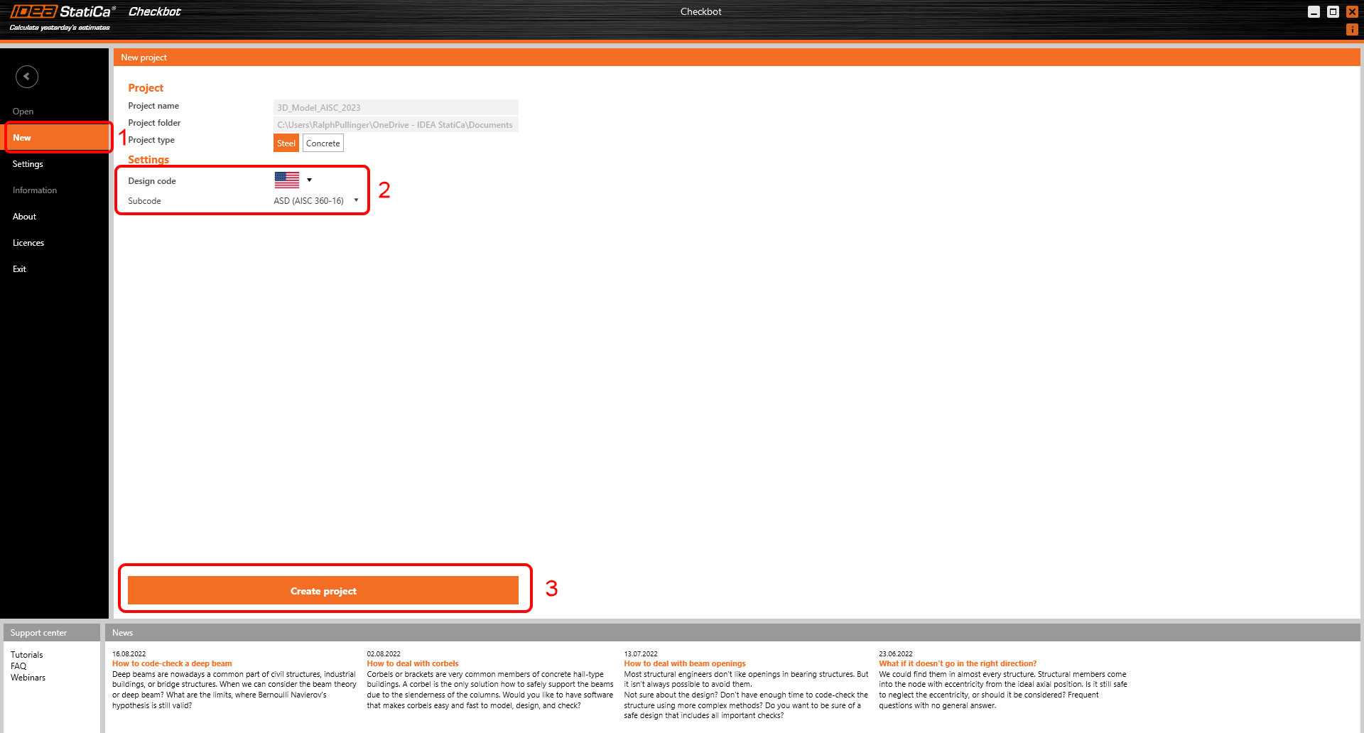
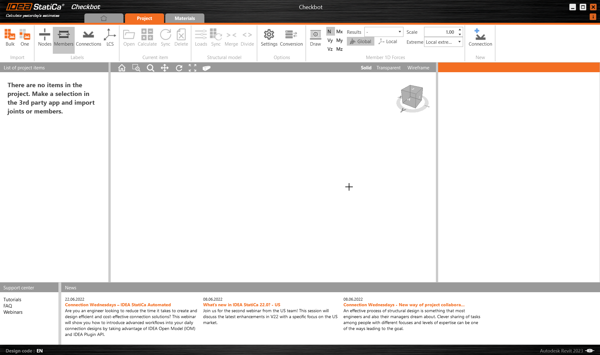
The new Checkbot project is ready to import connections from Autodesk Revit.
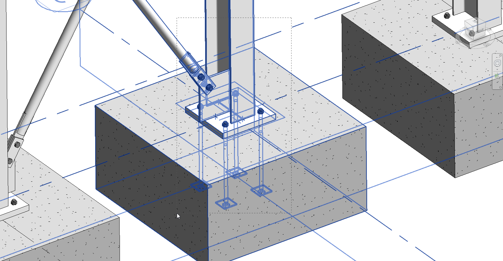
We are going to examine the baseplate and brace connection at the bottom of one of the internal columns.

This connection is actually two connections. One for the baseplate and one for the brace. The exception though is that the baseplate connection has been broken (exploded) into its component parts. This is due to current limitations of the connection interaction.
In Checkbot, select One from the Import panel.

The focus is switched back to Revit and you are asked to select a connection - select the brace connection.

You are then asked to select connection objects (these are the members and other items that make up the whole connection) - using a crossing window select the objects as shown.
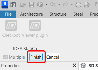
Finally select Finish in the top right of the ribbon area in Revit.
The last message box that appears asks if you want to import the recommended welds - respond Yes.

You may have to map materials and/or bolt grades. Go ahead and map these and press OK.

The members and connection placeholder are then imported into Checkbot.

Please see our tutorials about Checkbot and other BIM Links for more information about the Checkbot interface.
Geometry
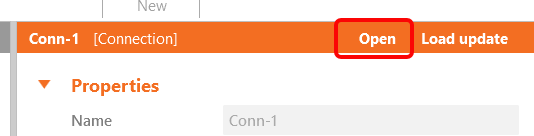
In Checkbot either select Open from the right hand panel
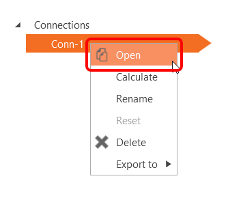
or right mouse click on the connection box and select Open
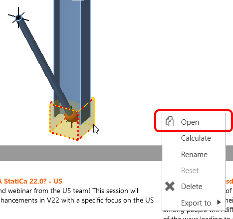
or right mouse click on the connection item and select Open.
If everything has been selected as shown you should have a view that looks like this:

This is where the combined geometrical and analytical approach is ideal as it creates an instantly useable connection in IDEA StatiCa. With previous tutorials based on either FEA or BIM solutions there is always one part that is missing.

However, we do have some editing to do before we can calculate. Although the brace is modeled, we still need to assign the correct Model Type - N-Vy-Vz. This is because there is a single bolt in use. The connection, as it stands, will still produce a mechanism because there is a single bolt passing through the sandwich and fin plates. To get over this we can either introduce more bolts (which makes the connection bigger and more costly) or use a small weld on the trailing edge.
Add a weld to each sandwich plate bottom edge as it touches the fin plate:

It is also incumbent on ourselves to point out some known limitations that there is when working with Revit.

- As a result of this connection export from Revit an extra plate is generated in Revit after the connection appears in Checkbot. This should obviously be deleted. Check back here for future updates!
- The tubular brace is cut by a negative volume and finally welded. However, there is a better way of doing this that gives better results: cut the brace by the plate and automatically weld one to the other. Turn off NVOL 1; adjust Cut Beam by Beam 1 to the following and finally turn off Weld 6.
- If you rotate the model you will see that two welds have come over as single sided fillet when they should be double sided. For Weld 1 and Weld 5 make them double sided.
- Edit the Anchors 1 operation so that the Shear is taken by the anchors and not by friction.

Given that the IDEA connection model originated from the Revit model there is an argument that the host information should be corrected first and then synchronized with IDEA (to keep the single-source-of-truth just that).
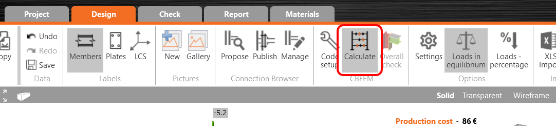
Now the model is ready to be calculated, press Calculate from the top ribbon:
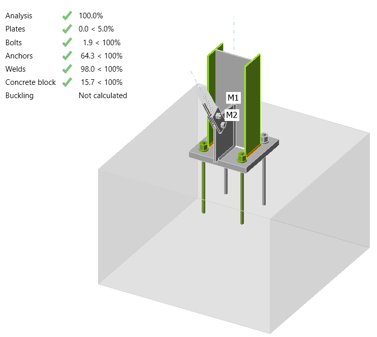
After a few moments the initial 'traffic-light' results will appear.
Before we go, we would also like to highlight the use of a generic connection in Revit. A generic connection is used as a placeholder - 'a connection goes here but I don't know what it looks like' or the actual connection is too complicated for Revit!

Switching to wireframe mode you can clearly see a green connection holder on top of a column with multiple beams framing in and out. Using a similar workflow to the baseplate and brace example this connection can be imported into Checkbot and edited with the Operations in IDEA StatiCa. The benefit of this workflow is not as big as with the previous example but it is a way to import the members and their results.

There will be times when modifications to the Revit model are required. The preferred workflow would be to make the desired geometrical changes in Revit, send the model for analysis, analyse and design for those changes before sending back any differences. Checkbot can then look for those changes.
모델 동기화
FEA/BIM 모델에서 부재 단면 크기나 하중 변경 등이 발생하는 경우가 있습니다. 이러한 변경 사항은 Checkbot과 FEA/BIM 모델 간에 동기화할 수 있습니다.
두 가지 방법이 있습니다:
- 현재 항목 동기화 (하나 이상의 접합부가 선택된 경우)
- 가져온 구조 모델 전체 동기화
이 기능을 테스트하려면 BIM 애플리케이션에서 부재 단면 크기나 형상을 변경하거나 하중 케이스 또는 조합 등을 수정하십시오: 선택한 기둥을 더 작은 단면으로 변경합니다.
Checkbot에서 설계된 연결(하나 이상일 수 있음)을 선택하고 현재 항목 패널에서 Sync를 선택합니다.

Checkbot 프로젝트가 업데이트되며, 연결 설계는 유지되지만 결과는 무효화됩니다. 기둥이 이제 업데이트되어 BIM 모델의 변경 사항과 일치하는 것을 확인할 수 있습니다.

현재 항목 패널에서 Calculate 를 선택하여 강조 표시된 연결에 대해 규정 검토를 다시 수행합니다. 모델의 큰 변경 사항은 영향을 받는 연결에 대해 추가적인 검증 단계가 필요할 수 있음을 유의하십시오(위 참조).

연결이 원하는 결과를 제공하지 않는 경우, 다시 열어 설계를 최적화할 수 있습니다(즉, 규정 검토에 실패하면 보강하거나 이용률이 너무 낮으면 경량화합니다).
You have successfully linked Autodesk Revit with IDEA StatiCa Connection via Checkbot. You have even explored features that allow the Revit workflow to extend beyond known, published connection types.