
Real hinge vs theoretical hinge
To ensure the compliance of the computational model with the real shape of the connection, we have to think about the point of application of the shear force, especially in the case of a hinge connection.
This is a schematic "real" shape of a structural connection (left) and its structural model used for the analysis (right).
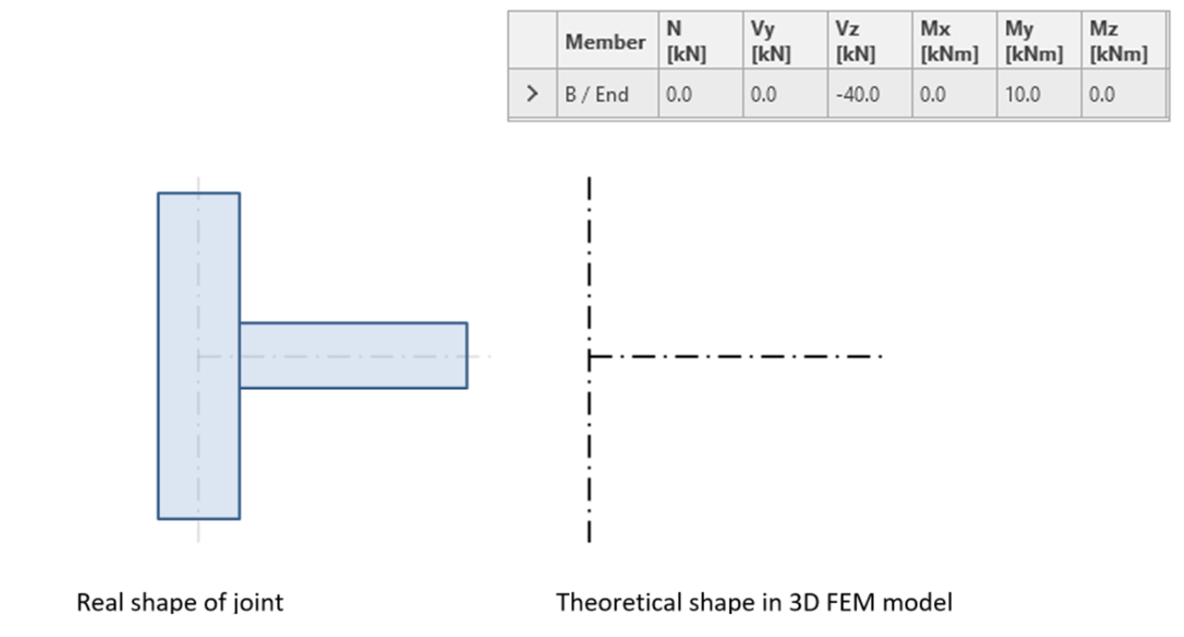
In IDEA StatiCa Connection, we define the nodal forces at every structural member. This is an example of a moment connection (with shear force and bending moment applied).

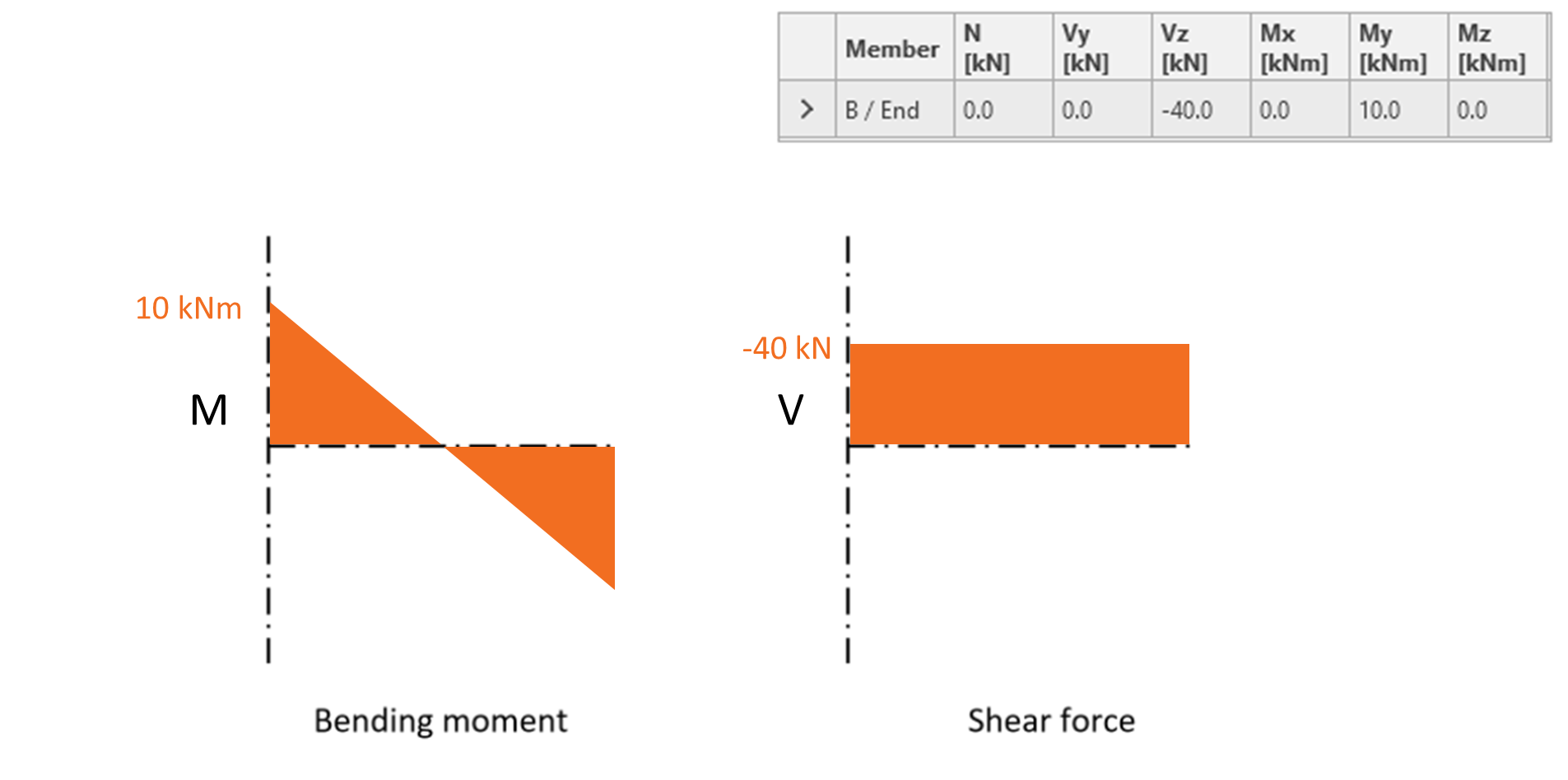
Corresponding diagrams of internal forces on the horizontal member connected with a moment connection. The value of the bending moment is also discussed in the Correct input of bending moment article.
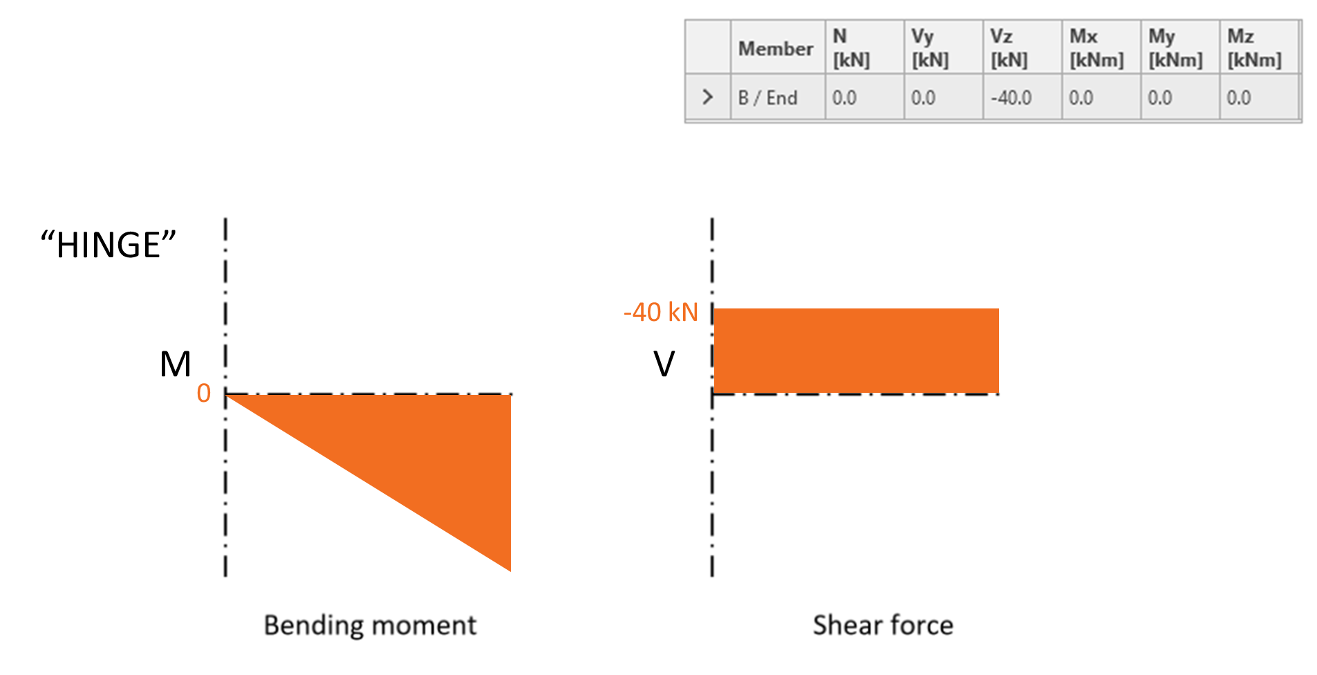
For hinge, the applied bending moment is equal to zero and the diagrams of internal forces on a horizontal member can look like this:
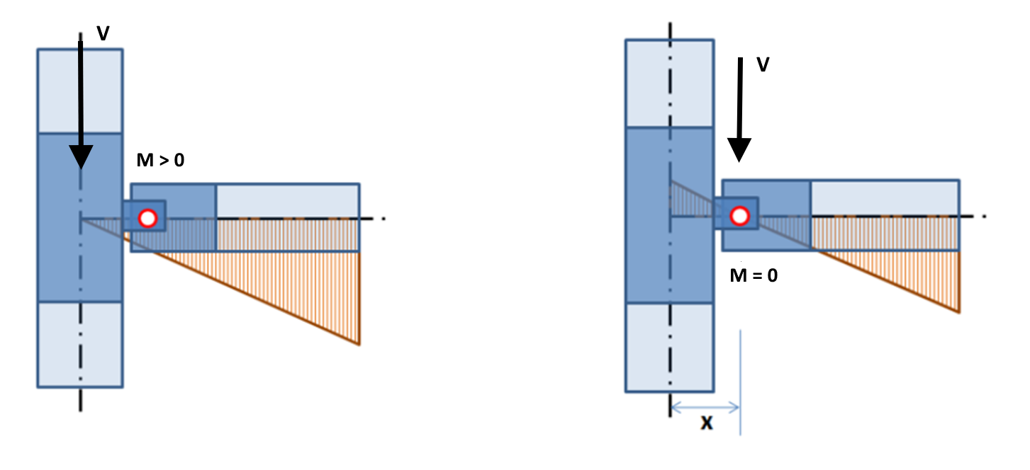
The above picture corresponds to an ideal situation where the theoretical hinge position is directly at the theoretical node. In reality, the actual point of rotation (hinge) is shifted from the point of the theoretical node (usually the intersection of the members' axes). We assume that for bolted connections, the point of rotation is at the center of the bolt group.
Now, let's compare the situation when the zero bending moment is considered to be at the node (left) and when we shift the position of the shear force (and thus the zero bending moment) to the actual point of rotation (right).
Setting the position of forces
In the application, the position of shear force can be defined in the Model section of the given Member. The difference between these two cases is shown here:

Left: Forces in Node Right: Forces in Bolts
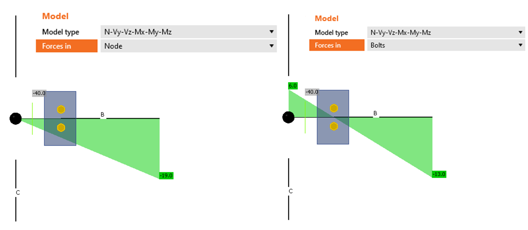
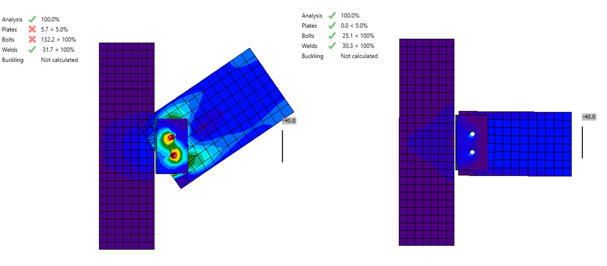
In the situation on the left, there is a bending moment at the point of the hinge which causes the member to rotate upwards. This moment (originated from the shear force which linearly grows from the node point) induces the incorrect behavior of the horizontal member.
We can easily fix the setup by moving the shear force to act at the position of the hinge. In such a case (the right picture), the horizontal beam deflects as expected.
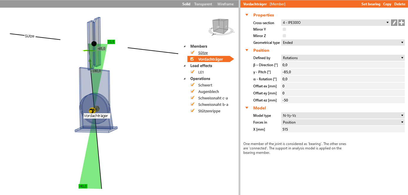
The third option is Forces in Position. For some operations, especially when creating a connection as an assembly of more basic operations (e.g. stiffening plate, cut, bolt grid), the function Forces in Bolts doesn't have any effect and there is no shift of the zero bending moment into the assumed hinge.
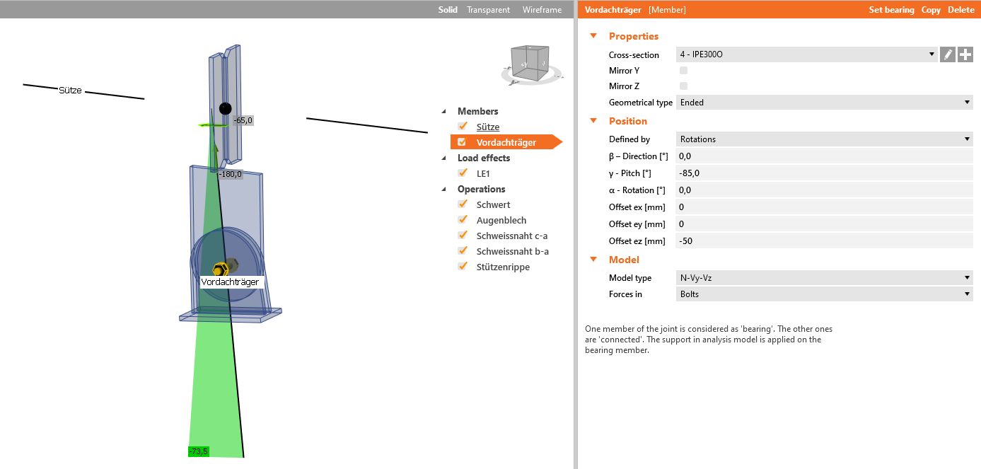
Therefore, the method Forces in Position must be chosen and the appropriate X distance must be input.
Webinar recording
See the recordings of our past webinars where the position of shear force is discussed.
The position of the nodal internal forces that we get from a structural model can be by eccentricities shifted from the origin. This effect underestimates the internal forces acting at the connection. Let's see how to change the position of internal forces directly in operation and avoid incorrect results.
Csatolt letöltések
- How to define correct load position (Forces in) (1).ideaCon (IDEACON, 38 kB)