
Passerelle pedonali
The idea was to create an adaptable space to host a diverse array of events throughout the year, accommodating the variable climatic conditions prevalent in the region, be it the inclemency of winter or the intensity of summer.
Central to the project is installing a roof canopy using a photovoltaic glass layer and extending it over the entire square. It is ingeniously designed to harness solar energy and generate a sustainable power supply for the operational needs of the market. With a collective expanse of 4,300 square meters, the canopy is strategically partitioned into two distinct platforms, namely the upper and lower platforms.


About the project
The primary framework comprises a series of steel trusses spanning a total distance of 45 meters, featuring a central span of 29.6 meters and cantilevers of 7.7 meters on each side of the roof. These trusses are arranged in parallel, maintaining a 7.4-meter spacing between them. The primary truss exhibits a variable height, reaching approximately 2.5 meters above the columns and 2 meters at the mid-span. Additionally, the structure incorporates tubular purlins to which the photovoltaic structural glass is affixed.
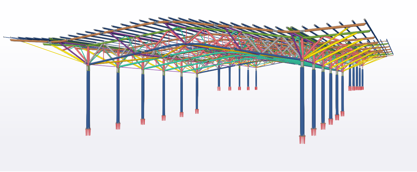
In accordance with architectural specifications, the entire structure was meticulously designed using circular hollow sections. The intricacies of the production process necessitated categorizing the steel structure under the EXC3 execution class as per the EN 1090-2 standard.
Footbridge 1 has a total length of 49.54 m, divided into two asymmetrical spans of 21 m and 29 m, with a continuous beam pattern on 3 supports. The cross-section is 2.50 meters wide, while the internal pathway is 1.80 meters wide.
The structure is composed of upper and lower beams made of T-profiles of different sizes and thicknesses, while UPN coupled profiles are used for columns and diagonals. A combination of welded and bolted connections between these structural elements was designed as rigid. Joists and strut braces ensure the overall rigid behavior of the structure and prevent the possible buckling of the upper beams. In the transverse direction, a rigid node frame system between columns and beams was used.
Footbridge 1 is 49.54 a 49.54-meter-long continuous beam with three supports, with two asymmetrical spans of 21 and 29 meters. The cross-section is 2.50 meters wide, while the internal pathway is 1.80 meters wide. The structure includes T-profile beams and UPN-profile columns and diagonals, with embedded beams, joists, and strut braces ensuring rigidity and preventing buckling. The longitudinal direction uses a braced system, while the transverse direction features rigid node frames.
The walking surface consists of ribbed metal plates on joists, with connections made by bolting and welding.
Footbridge 2 features a 46.4 m radius of curvature and spans 43.7 m with three asymmetrical segments of 9 m, 17 m, and 17.5 m. The bridge has no slopes, maintaining a single elevation, with a 2.50 m footprint and a 1.80 m internal span. It consists of T-profile beams, UPN-profile columns, and diagonals. Connections are reinforced with embedded beams, joists, and strut braces to prevent buckling. The longitudinal direction uses a braced system, and the transverse direction has rigid node frames. The walking surface is ribbed metal slabs resting on joists, with bolted and welded connections.
Engineering challenges
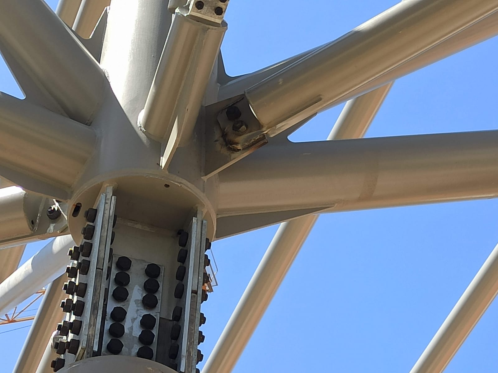
The steel framework posed numerous challenges, with many complexities. Most of them come from the requirements of the project architect and the fact that the whole structure was designed entirely from CHS profiles. For CHS profiles, there is, in general, very little guidance in codes, and more advanced numerical solutions are usually needed. This is especially the case with such complex geometry, resulting in nodes where structural members from different directions converged simultaneously.
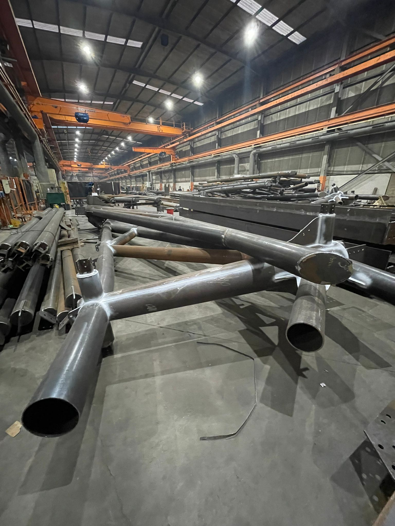
Also worth mentioning, there was the issue of the need for transportability in an area with stringent restrictions on heavy truck circulation, which posed a significant hurdle. Consequently, the main trusses, each spanning 45 meters, had to be divided into smaller segments capable of being pre-assembled on-site before the final erection, navigating the logistical constraints effectively.
Moreover, the imposition of pre-cambers in the main trusses became imperative to precisely regulate deflections within the steel structure. This measure was crucial given the glass cover's sensitivity to substantial deflections, demanding meticulous control over the structural elements.
Solutions and results
Due to the complex geometry of the connections, the approach adopted in their design was based on an iterative process. This would be very time-consuming due to tedious modeling if it weren't for the BIM link option between IDEA StatiCa and Tekla Structures. IDEA StatiCa Connection was then used mainly to analyze the behavior of the connections.

Portugal
In the first phase, the connections were dimensioned from an analytical perspective and even with an important component of empirical knowledge. The result of this design phase was incorporated into the BIM model, developed in Tekla Structures, and its design was made compatible with the node geometry and the structure singularities.
In the second phase, the refined geometry was directly imported from Tekla Structures into IDEA StatiCa, and all safety checks and adjustments were carried out to reach the final design.

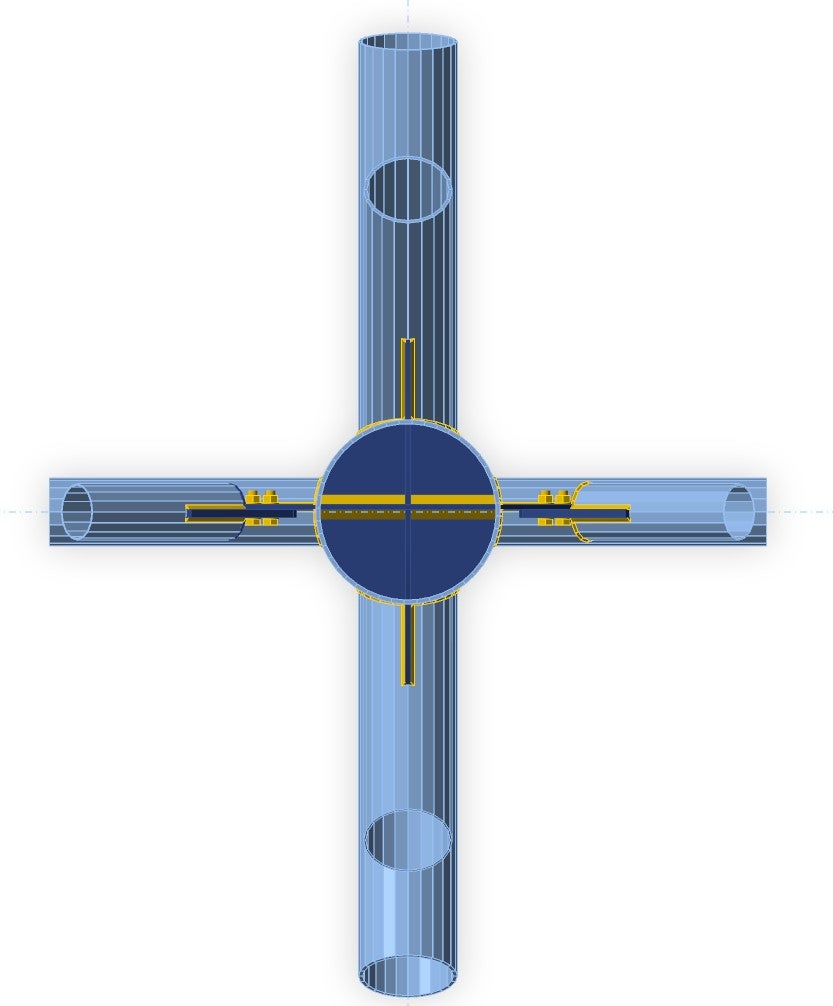
In addition to the classic EPS analysis, the CHS, as with other thin-walled profiles, had to be checked for buckling shape. And unfortunately, due to many connected bars to the main column, a problem with buckling appeared. However, the engineering team from Steelplan (José Manuel Silva, Joao Pimenta) was able to come up with an elegant solution that met the architectural requirements and ensured the safety of the structure.

Portugal
Originally gusset plates welded to the surface were changed to plates that go through the entire cross-section of the main column, forming a "cross" inside the hollow section. This allowed the dimensions of the main elements to remain almost unmodified from the original design.
After some interactions, the final geometry was perfectly defined, and all the safety checks, according to Eurocodes, were carried out.

About Steelplan
Steelplan develops its activity in steel structural design and detail, BIM modeling, and work preparation for construction steelwork companies. Steelplan is based in Braga, north of Portugal, a very prominent region of construction steelwork in Portugal.
The company's experience is based on the dynamics and knowledge of its engineers with a large experience in the metalworking industry and their involvement in reference projects at a national and international level.