Prequalified joints for seismic applications
12.1 EQUALJOINTS project
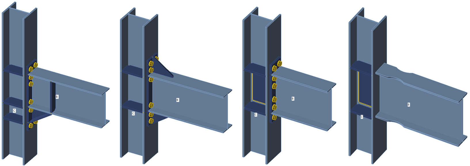
The European research project EQUALJOINTS provides prequalification criteria of steel joints for the next version of EN 1998-1. The research activity covered the standardization of design and manufacturing procedures for a set of bolted joint types and a welded reduced beam section with heavy profiles designed to meet different performance levels. There was also the development of a new loading protocol for European prequalification, representative of European seismic demand. The experimental campaign devoted to the cyclic characterization of both European mild carbon steel and high strength bolts achieved the required behavior for four types of pre-qualified joints: haunched bolted joints, unstiffened extended end plate bolted joints, stiffened extended end plate bolted joints, and welded reduced beam section joints; see Fig. 12.1.1. The results experimentally reached within the EQUALJOINJTS project are summarised in (Stratan et al. 2017) and (Tartaglia and D’Aniello, 2017).
Fig. 12.1.1 Structural joints prequalified in EQUALJOINTS project
12.2 End plate joints
The extended stiffened end plate bolted connections are most common among European steel fabricating industries and are widely used in European practice as moment-resistant joints in low and medium-rise steel frames thanks to the simplicity and the economy of fabrication and erection. The design criteria and related requirements for bolted extended stiffened end plate beam-to-column joints are deeply investigated and critically discussed and currently codified in EN 1998-1:2005 based on a parametric study based on finite element analyses. Unfortunately, capacity design procedure was developed only in the framework of component method. It also accounts for the presence of ribs and is able to control the joint response for different performance levels.
Unstiffened extended end plate joints are commonly used in steel construction to connect steel I or H beam to steel I or H column in the case where significant bending moments have to be transferred. This configuration allows an easy erection by bolting while welding the end plate to the beam is automated in shop. The bending resistance of the connection is mostly lower than the bending resistance of the connected members. Therefore, such joints are considered as partial strength. Reaching an equal strength situation, in which the plastic resistance of the joint is roughly equal to the plastic resistance of the beam section, may be achieved through appropriate design. Their ductility in bending depends highly on the detailing of the joints, which influences the failure mode (Jaspart, 1997). If the joint component governing the failure is a ductile one, and if the resistance of the brittle active components is significantly higher, a ductile joint response may be reached. In the opposite case, no reliance should be made on the capacity of the joint to form plastic hinges and redistribute internal forces to absorb energy in a seismic area.
For the welded reduced beam section moment resisting connections, also referred to as dog-bone, two main strategies were adopted by strengthening the connection or weakening the beam. Among these two options for the profile of section reduction, the radius cut tends to exhibit a relatively more ductile behavior, delaying the ultimate fracture (Jones et al. 2002). However, the work showed that reduced beam section members are more prone to lateral-torsional buckling due to the decreased area of their flanges. Further experimental and analytical research focusing on the application of deep columns (Zhang and Ricles, 2006) indicated that the presence of a composite floor slab may greatly reduce the amount of twisting developing in the column, as it offers bracing to the beam and reduces the lateral displacement of the bottom flange.
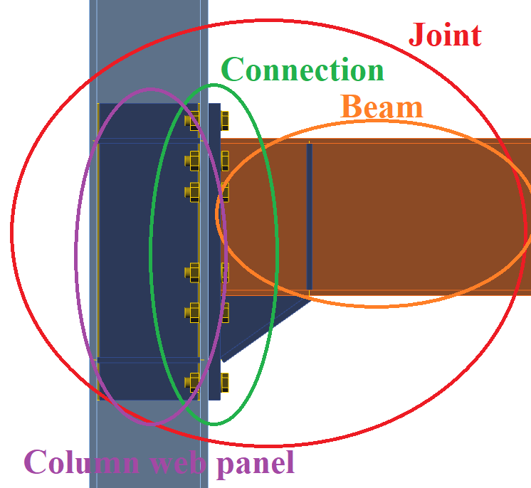
According to the design procedure developed within the project EQUALJOINTS, the joint comprises three macro-components: the column web panel, the connection zone, and the beam zone; see Fig. 12.2.1. Each macro-component is individually designed according to specific assumptions, and then capacity design criteria are applied in order to obtain three different design objectives defined to assess the joint: full strength, equal strength, and partial strength joints. Full strength joints are designed to guarantee the formation of all plastic deformations into the beam, which is consistent with EN 1998-1:2005 strong column – weak beam capacity design rules. Equal strength joints are theoretically characterized by the contemporary yielding of all macro-components, i.e. connection, web panel, and beam. Partial strength joints are designed to develop the plastic deformation only in the connection or column web panel. According to the resistance of the connection and column web panel macro-components for both equal and partial strength joints, an additional classification can be introduced. For strong web panel, the plastic demand is concentrated in the connection for partial strength joint or in the connection and in the beam for equal strength joint. In balanced web panel, the plastic demand is distributed between the connection and the column web panel for partial strength joint and in the connection, web panel, and the beam for equal strength joint. For weak web panel, the plastic demand is concentrated in the column web panel for partial strength joint or in the web panel and in the beam for equal strength joint.
Fig. 12.2.1 Division of joint into macro components
The joint ductility depends on the type of failure mode and the corresponding plastic deformation capacity of the activated component. Deformation capacity may be roughly predicted by satisfying the developed criteria for CM or more precisely calculated by CBFEM. The examples of design of two prequalified joint configurations described in EQUALJOINJTS project materials and in ANSI/AISC358-16 standard are presented below considering the behavior of macro components separately.
12.2.1 Validation
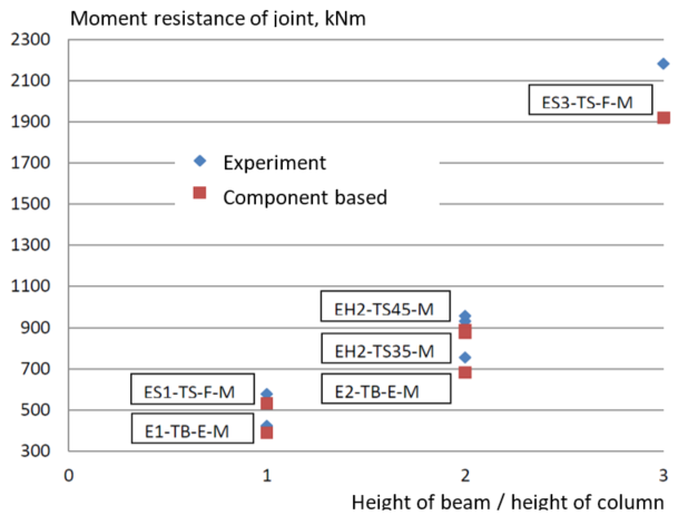
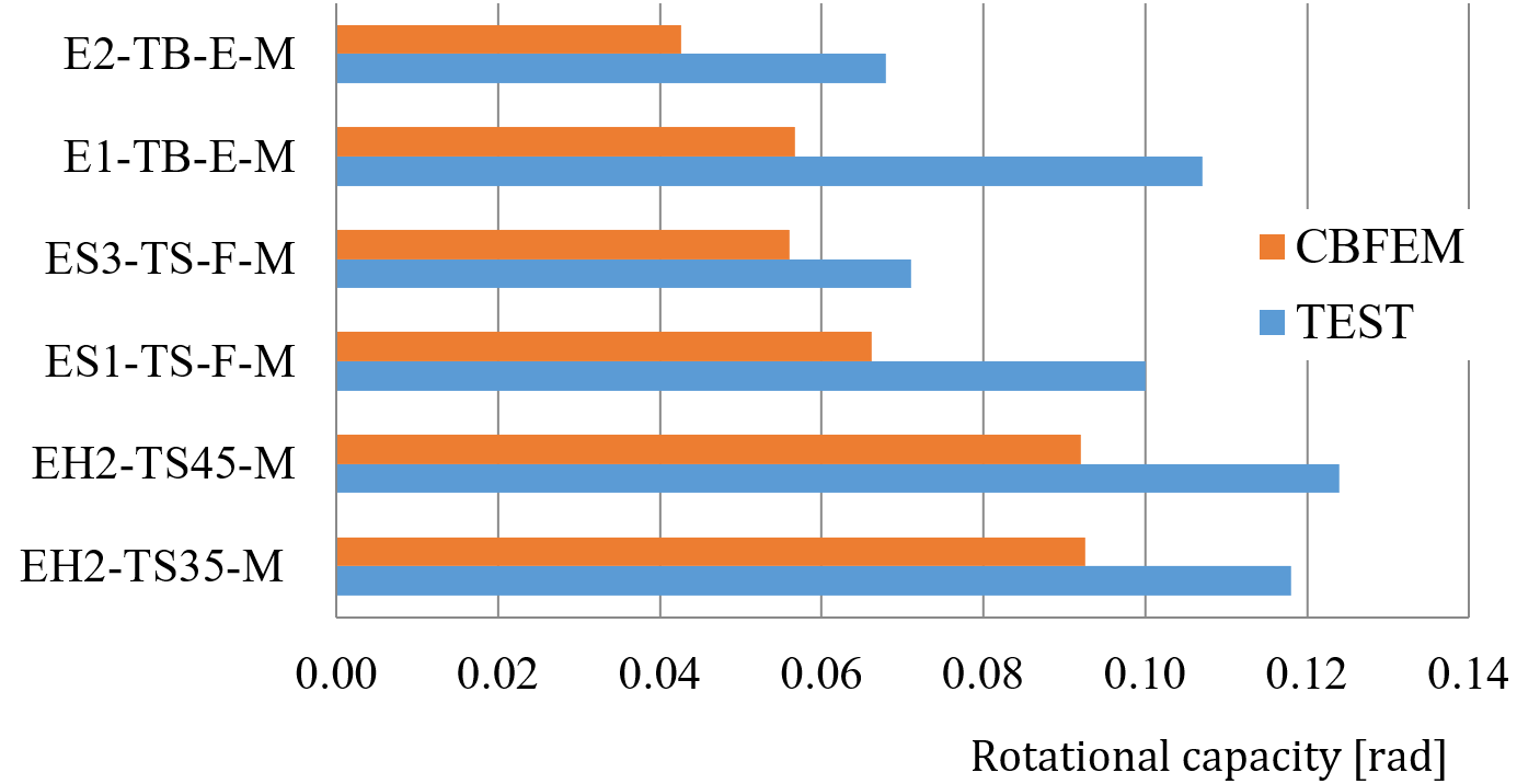
The CBFEM models of rigidity, load-bearing capacity, and deformation capacity of pre-qualified joints were validated by Montenegro (2017) on a set of experiments available from EQUALJOINT project. The examples of structural solutions are in Fig. 12.2.2. The results of validation of the failure mode are shown in Fig. 12.2.3. The summary of validation of resistance and deformation capacity for 15 % strain are shown in Figs 12.2.4 and 12.2.5.
Fig 12.2.2 Joints used for validation and verification a) EH2- TS-35-M and EH2-TS-45-M, b) ES1-TS-F-M and ES3-TS-F-M, c) E1-TS-E-M and E2-TS-E-M
Fig. 12.2.3 Validation of failure mode of CBFEM on the extended end plate joints with haunch E1-TS-F-C2 (Tartaglia and D’Aniello, 2017)
Fig.12.2.4 Validation of resistance of CBFEM on experiments from EQUALJOINTS project
Fig. 12.2.5 Validation of rotational capacity of CBFEM on experiments from EQUALJOINTS project
12.2.2 Verification
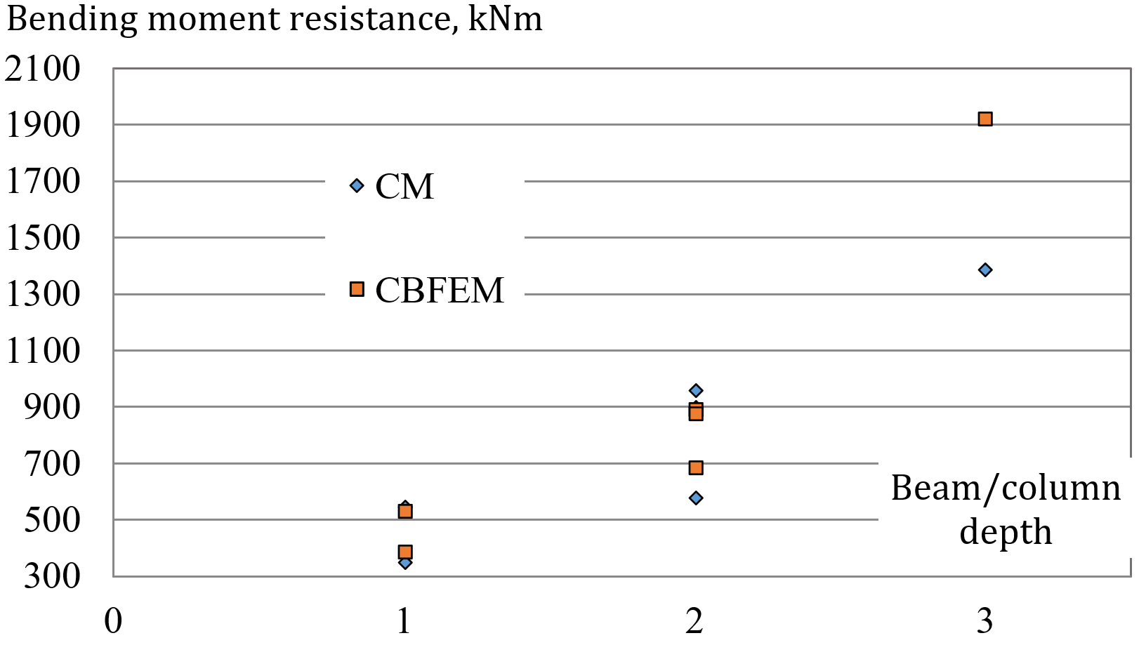
The CBFEM model was verified to CM according to Ch. 6 in EN 1993-1-8:2006. The selection of results is presented in Tab.12.2.1 and Fig 12.2.6. The results show the loss of accuracy of CM for larger joints, where the rough assumption of lever arm is guiding the accuracy.
Tab. 12.2.1 Verification of CBFEM to CM
| Typology | Resistance | |||
| # | CM | CBFEM | CBFEM/CM | Decisive component |
| MR [kNm] | MR [kNm] | [%] | ||
| Haunched joint | ||||
| EH2-TS35-M | 901,2 | 889 | 1 | Endplate in bending |
| EH2-TS45-M | 959,3 | 875 | 10 | Endplate in bending |
| 4.2 | 876,1 | 1 016 | −16 | Column flange in bending |
| 264 | 545,4 | 573 | −5 | Column flange in bending |
| 267 | 1 998,9 | 2 100 | −5 | Endplate in bending |
| Extended stiffened joint | ||||
| ES1-TS-F-M | 547,5 | 533 | 3 | Column flange in bending |
| ES3-TS-F-M | 1389 | 1 920 | −27 | Column flange in bending |
| Extended unstiffened joint | ||||
| E1-TB-E-M | 347,8 | 389 | −11 | Endplate in bending |
| E2-TB-E-M | 577,0 | 681 | −15 | Endplate in bending |
Fig. 12.2.6 Verification of resistance of CBFEM to CM
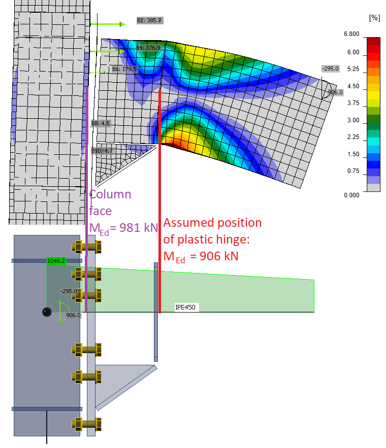
Three one-sided haunched joints are described in more detail in (Landolfo et al. 2017) and (Equaljoints application). The joints are loaded by both sagging and hogging bending moments and corresponding shear load. The column webs are reinforced by doublers, so the decisive components are T-stubs of either end plate or column flange. The axes of rotation are assumed at the center of the upper beam flange for sagging bending moment and in the middle of the haunch for hogging bending moment. The position of plastic hinge is assumed at the face of the stiffening plate at the end of the haunch. The bending moment at the column face used for check of the connection is increased by the corresponding shear load; see Fig. 12.2.7.
Fig. 12.2.7 Position of plastic hinge, course of bending moment in the haunched joint
Tab. 12.2.2 Resistance of components by CM for haunched joints
| Resistance of components by CM | #4.2 (IPE450 to HEB340) | #264 (IPE360 to HEB280) | #267 (IPE600 to HEB500) |
| Moment at plastic hinge [kNm] | 906 | 543 | 1869 |
| Shear load [kN] | 295 | 148 | 561 |
| Moment at column face [kNm] | 981 | 573 | 2105 |
| Haunch resistance [kNm] | 956 | 582 | 1903 |
| Shear acting on column web [kN] | 1581 | 1035 | 2447 |
| Column web in shear resistance [kN] | 1632 | 1203 | 2774 |
| T-stub - end plate - hogging moment [kNm] | 1019 | 573 | 1999 |
| T-stub - end plate - sagging moment [kNm] | 1081 | 697 | 2318 |
| T-stub - column flange - hogging moment [kNm] | 876 | 545 | 2015 |
| T-stub - column flange - sagging moment [kNm] | 929 | 580 | 2107 |
The strain-hardening factor was chosen 1,2 as suggested by EN 1993-1-8:2006 and Equaljoints project final report (EN 1998-1:2005 suggests value 1,1). Overstrength factor was assumed 1,25 (Landolfo et al. 2017). All steel was grade S355. The resistances of individual components are summarized in Tab. 12.2.2. The checks in bold are failing. Note that haunch resistance is the plastic resistance of the beam section with the haunch at end plate. The strength of the beam is assumed increased by overstrength factor at the location of plastic hinge but not at the end plate. If the overstrength factor was used at the end plate as well, this resistance would be higher. Therefore, the next lowest resistance, the T-stub – end plate, was assumed to govern the joint resistance of joint No. 267. None of the investigated joints meets the requirement for full-strength joint. However, the resistance is very close, and the joints are equal-strength. The column web panel is in all cases strong.
The governing failure mode by CBFEM is failure of bolts with yielding of plates, mainly end plate, column flange, and haunch. According to CBFEM, joints No. 4.2 and No. 264 are full-strength and joint No. 267 equal-strength. Column web panels are strong in all cases.
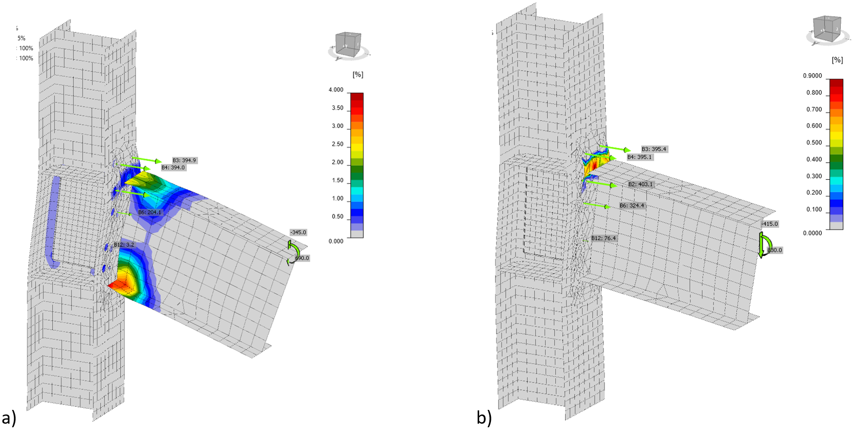
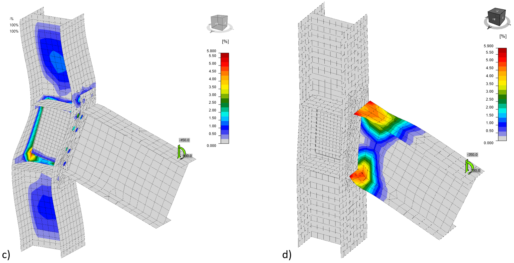
Fig. 12.2.8 The strains at resistance for a) the whole joint, b) the macro-component bolted end-plate connection only c) the macro-component column web panel in shear with web doublers only, d) the macro-component beam only
12.2.3 Unstiffened extended end-plate joints
For sensitivity study, a prequalified unstiffened extended end-plate joint was selected. The beam IPE 450 is connected to column HEB 300 by an extended end plate 25 mm thick with twelve M30 10.9 bolts, with and without web doubler 10 mm thick. Steel grade S 355 was used for all plates. To determine the contribution of each macro component separately, the material diagram of the selected macro component was elastoplastic, while the rest of the joint was with only elastic material diagram. The strains at the resistance of the whole joint, the column web panel in shear with web doublers only, and the bolted end-plate connection only are compared to the beam macro-component only in Fig. 12.2.8. The influence of each macro-component on the behavior of the joint is presented in Fig. 12.2.9, where column web panel with and without web doublers is shown. The joint behavior shows higher resistance of the connection macro-component.
Fig. 12.2.9 Influence of macro-components, the column web panel with doublers in shear,
the bolted end-plate connection and beam to the behavior of the whole joint
12.2.4 Location of compression center
For end-plate joints, EN 1993-1-8:2006 specifies that the compression center is located in the middle of the thickness of beam flange, or at the tip of the haunch in case of haunched joints. Experimental and numerical results showed that the location of compression center depends on both the joint type and the rotation demand due to the formation of plastic modes with different engagement of each joint component (Landolfo et al. 2017). According to the proposed CM design procedure and based on both experimental and numerical results, contact at about the centroid of the section made by the beam flange and the rib stiffeners is expected, for the stiffened endplate joints or at about 0,5 the haunch height in case of haunched joints. This rough assumption is précised by CBFEM procedure, which gives correct values during loading and initial yielding of parts of a joint.
The presented results show the good accuracy of CBFEM verified to ROFEM validated to EQUALIJOINTS experiments and CM. It brings the possibility to consider the behavior of macro-components separately and the position of neutral axes accurately according to the loading/plastification.
12.3 Welded reduced beam section joint
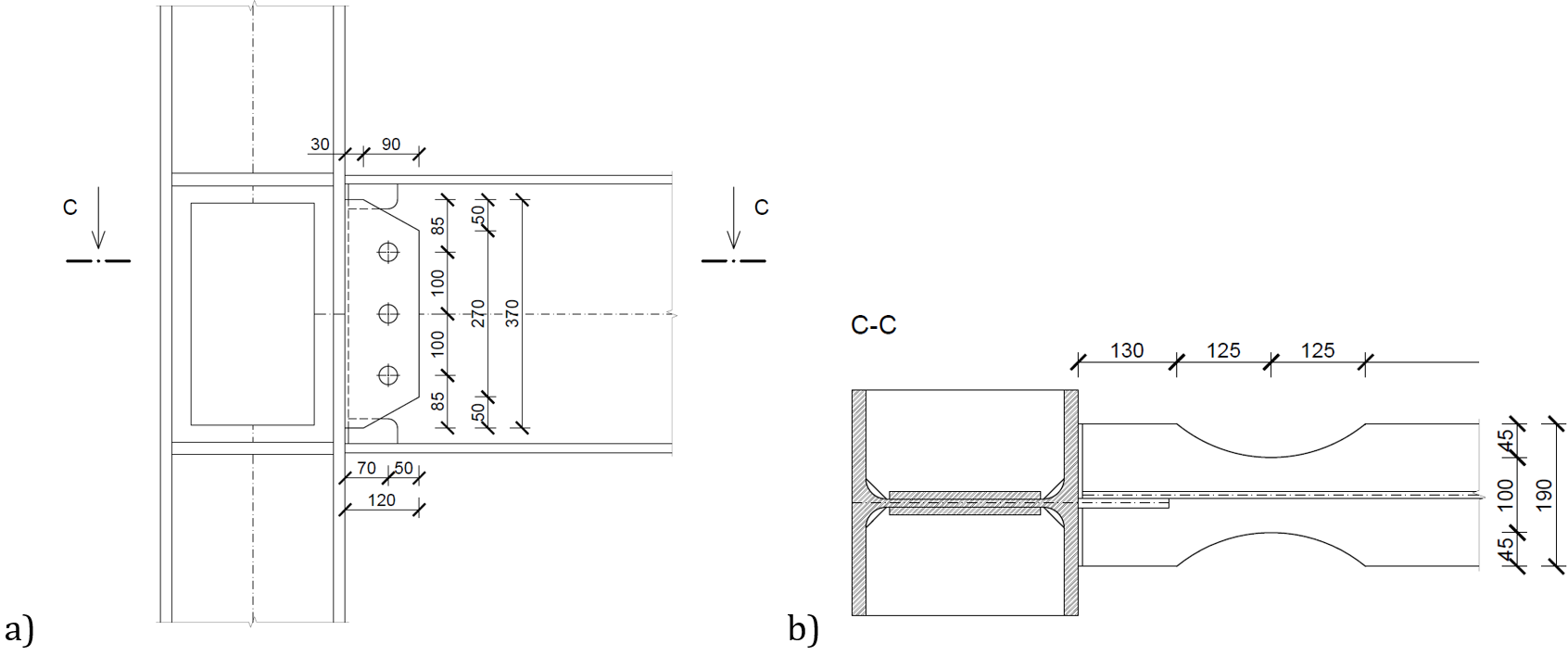
A prequalified welded reduced beam section joint according to ANSI/AISC 358-16 was selected for this study. The beam IPE 450 is connected to column HEB 300 by butt welds at flanges and fin plate 12 mm thick with three preloaded M30 10.9 bolts, with and without web doubler 10 mm thick; see Fig. 12.3.1. All used steel is grade S355.
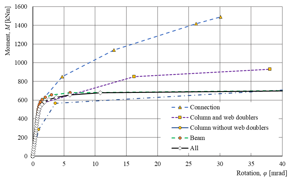
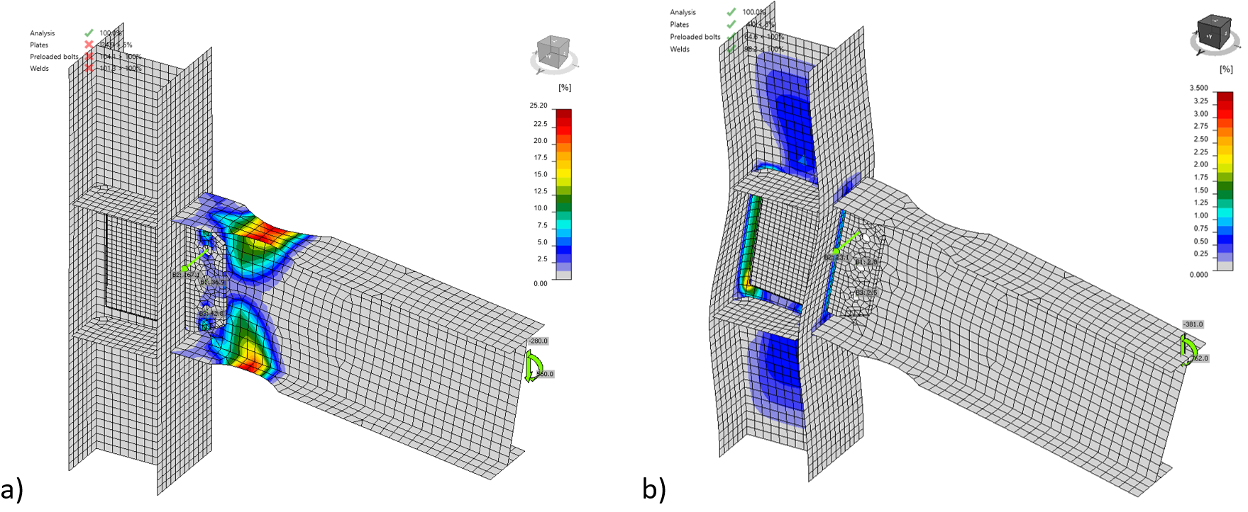
The strains at the ultimate resistance of the whole joint and macro component column web panel in shear with web doublers only are shown in Fig. 12.3.2. The influence of each macro-component to the behavior of the joint is presented in Fig. 12.3.3, where column web panel with and without web doublers is shown. The joint shows that the resistances of the joint macro-components are well-optimized.
Fig. 12.3.1 Reduced beam section joint, a) beam with reduced section, b) the column web panel with doublers in shear, the bolted end plate connection,
Fig. 12.3.2 The strains at resistance for a) the whole joint and b) the macro component column web panel with doublers in shear only
Fig. 12.3.3 Influence of macro-components on the behavior of the whole joint on M-φ diagram
References
EN 1993-1-8, Eurocode 3, Design of steel structures – Part 1-8: Design of joints, CEN, Brussels, 2005.
Jones S.L., Fry GT., Engelhardt M.D. Experimental evaluation of cyclically loaded reduced beam section moment connections. Journal of Structural Engineering. 128 (4), 441–451, 2002.
Landolfo R. et al. Design of Steel Structures for Buildings in Seismic Areas, ECCS Eurocode Design Manual. Wiley, 2017.
Stratan A., Maris C, Dubina D, and Neagu C. Experimental prequalification of bolted extended end plate beam to column connections with haunches. ce/papers, 1(2–3), 414–423, 2017.
Tartaglia R, D’Aniello M. Nonlinear performance of extended stiffened end-plate bolted beam-to-column joints subjected to column removal. The Open Civil Engineering Journal Vol 11, Issue Suppl-1, 369–383, 2017.
Zhang X., Ricles J.M. Experimental evaluation of reduced beam section connections to deep columns. Journal of Structural Engineering. 132 (3), 346-357, 2006.

