
Beam or column web with concentrated forces
Description
This article describes the resistance of beam or column web loaded by a concentrated force, typically a column web loaded by a bottom flange of a beam loaded by bending moment.

Figure 1. Examples of web loaded by a concentrated force
The study presents numerical models in IDEA StatiCa Connection and IDEA StatiCa Member and includes all three types of available numerical analyses:
- Materially nonlinear analysis (MNA)
- Linear buckling analysis (LBA)
- Geometrically and materially nonlinear analysis with imperfections (GMNIA) - available only in Member
The study is prepared for a member loaded by concentrated force from one side or two sides. Varying parameters of the member are:
- standard hot-rolled cross-sections HEA and HEB,
- welded cross-sections with varying,
- web thickness,
- flange thickness,
- flange width,
- Added end plate with varying thickness.
It is assumed that web sidesway buckling of the member is restrained.

Figure 3. Web sidesway buckling (taken from Eurocode EN 1993-1-8)
Analytical model
Analytical models assume load distribution angle through the member flange thickness and fillet radius or fillet weld and end-plate thickness, if applicable with an angle of 1:2.5. An effective web width is calculated and this web segment is assumed to resist the concentrated force.

Figure. Effective width for an end-plate connection according to Eurocode
Eurocode (EN 1993-1-8 – Cl. 6.2.6.3)
Eurocode checks two failure modes:
- Web yielding
\[F_{c,wc,Rd} = \frac{\omega k_{wc} b_{eff,c,wc} t_{wc} f_{y,wc}}{\gamma_{M0}} \]
- Web crippling
\[F_{c,wc,Rd} = \frac{\omega k_{wc} \rho b_{eff,c,wc} t_{wc} f_{y,wc}}{\gamma_{M1}} \]
where:
- \(\omega\) – reduction factor to allow for the possible effects of interaction with shear in the column web panel according to Table 6.3
- \(b_{eff,c,wc} \) – effective width of column web in compression:
- for a welded connection: \(b_{eff,c,wc} = t_{fb} + 2 \sqrt{2} a_b + 5 (t_{fc}+s) \)
- for bolted end-plate connection: \(b_{eff,c,wc} = t_{fb} + 2 \sqrt{2} a_p + 5 (t_{fc}+s) + s_p \)
- for bolted connection with angle flange cleats: \(b_{eff,c,wc} = t_a + 0.6 r_a + 5 (t_{fc}+s)\)
- sp – length obtained by dispersion at 45° through the end-plate (at least tp and, provided that the length of end-plate below the flange is sufficient, up to 2tp
- s – radius of fillet or fillet weld throat thickness
- for a rolled I or H section: \(s=r_c\)
- for a welded I of H section \(s=\sqrt{2}a_c\)
- \(\rho\) – reduction factor for plate buckling:
- if \(\bar{\lambda_p} \le 0.72\): \(\rho=1.0\)
- if \(\bar{\lambda_p} > 0.72\): \(\rho=(\bar{\lambda_p}-0.2)/\bar{\lambda_p}^2\)
- \(\bar{\lambda_p} = 0.932 \sqrt{\frac{b_{eff,c,wc}d_{wc}f_{y,wc}}{Et_{wc}^2}}\) – plate slenderness
- dwc – height of the column web between fillets
- for a rolled I or H section: \(d_{wc}=h_c-2(t_{fc}+r_c)\)
- for a welded I or H section: \(d_{wc}=h_c-2(t_{fc}+\sqrt{2}a_c)\)
- kwc – reduction factor taking into account stress in the column web by normal force or bending moment:
- when stress in the web \(\sigma_{com,Ed} \le 0.7 f_{y,wc}\): \(k_{wc}=1.0\)
- when \(\sigma_{com,Ed} > 0.7 f_{y,wc}\): \(k_{wc}=1.7-\sigma_{com,Ed}/f_{y,wc}\)
- fy,wc – web yield strength
- \(\gamma_{M0} = 1.0\) – partial safety factor for yielding
- \(\gamma_{M1} = 1.0 \) – partial safety factor for buckling
- \(\beta\) – transformation parameter

Figure 4. Explanation of variables used in formulas for column web yielding and crippling (taken from EN 1993-1-8)

Figure 5. Reduction factor \(\omega\) (taken from EN 1993-1-8)
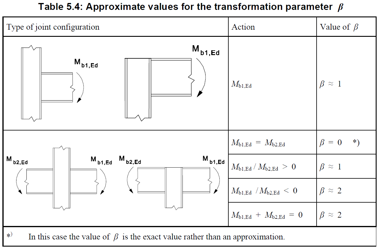
Figure 6. Transformation parameter \(\beta\) (taken from EN 1993-1-8)
AISC (AISC 360-16 – J10.2 and J10.3)
Compared to the Eurocode, there are no reduction factors for significant stress in the web by normal force or bending moment (factor kwc) and reduction factor due to shear in the web (factor \(\omega\)). On the other hand, AISC includes a reduction by 50% when the concentrated force is applied at the member end. It means that for standard cases, the resistances according to both codes are very similar using the same approach, but for limit cases, the resistances may very much differ.
Web local yielding is described in section J10.2.
When the concentrated force to be resisted is applied at a distance from the member end that is greater than the full nominal depth of the member, d:
\[\phi R_n = \phi F_{yw}t_w(5k+l_b)\]
When the concentrated force to be resisted is applied at a distance from the member end that is less than or equal to the full nominal depth of the member, d:
\[\phi R_n = \phi F_{yw}t_w(2.5k+l_b)\]
where:
- \(phi=1.0\) – resistance factor
- Fyw – specified minimum yield stress of the web material
- k – distance from outer face of the flange to the web toe of the fillet
- lb – length of bearing (not less than k for end beam reactions)
- tw – thickness of web
Web local crippling is described in section J10.3.
When the concentrated compressive force to be resisted is applied at a distance from the member end that is greater than or equal to d/2:
\[\phi R_n = \phi 0.8t_w^2 \left [ 1+3 \left ( \frac{l_b}{d} \right ) \left ( \frac{t_w}{t_f} \right )^{1.5} \right ] \sqrt{\frac{EF_{yw}t_f}{t_w}} Q_f\]
When the concentrated compressive force to be resisted is applied at a distance from the member end that is less than d/2:
- For lb/d ≤ 0.2:
\[\phi R_n = \phi 0.4t_w^2 \left [ 1+3 \left ( \frac{l_b}{d} \right ) \left ( \frac{t_w}{t_f} \right )^{1.5} \right ] \sqrt{\frac{EF_{yw}t_f}{t_w}} Q_f\]
- For lb/d > 0.2:
\[\phi R_n = \phi 0.4t_w^2 \left [ 1+3 \left ( \frac{4l_b}{d}-0.2 \right ) \left ( \frac{t_w}{t_f} \right )^{1.5} \right ] \sqrt{\frac{EF_{yw}t_f}{t_w}} Q_f\]
where:
- \(\phi = 0.75\) – resistance factor
- d – full nominal depth of the member
- Qf = 1.0 for wide-flange sections and for HSS (connecting surface) in tension; Qf = as given in Table K3.2 for all other HSS conditions
Web compression buckling is described in section J10.5.
\[\phi R_n = \phi \left ( \frac{24t_w^3 \sqrt{EF_{yw}}}{h} \right ) Q_f \]
where:
- \(\phi = 0.9\) – resistance factor
When the pair of concentrated compressive forces to be resisted is applied at a distance from the member end that is less than d/2, Rn shall be reduced by 50%.
Numerical model
The numerical models of members in IDEA StatiCa do not have any fillet radius between the web and the flange, and there is nothing stiffening the member in the longitudinal direction. The yielding resistance in IDEA StatiCa is determined purely by finite element analysis and strain check limited by 5%. Linear buckling analysis provides critical load multiplication factor, \(\alpha_{cr}\). If this factor is smaller than 3, the user is warned that buckling and crippling resistance will govern over yielding resistance. Buckling and crippling resistance may be determined by GMNIA analysis or a General method using a combination of LBA and MNA.
Eurocode provides buckling curve for web panel and the limit of relative slenderness, \(\bar{\lambda_p} =0.72\). The limit of critical load multiplication factor, \(\alpha_{cr}\) may be calculated:
\[ \alpha_{cr,lim} = \frac{1}{\bar{\lambda_p}^2} = \frac{1}{0.72^2} = 1.93 \]
That means there should be sufficient safety when setting the limit of \(\alpha_{cr}\) to 3.
Note that in the second generation Eurocode draft prEN 1993-1-8:2020, the limit of relative slenderness is changed:
- \(\rho\) – reduction factor for plate buckling:
- if \(\bar{\lambda_p} \le 0.673\): \(\rho=1.0\)
- if \(\bar{\lambda_p} > 0.673\): \(\rho=(\bar{\lambda_p}-0.22)/\bar{\lambda_p}^2\)
To calculate \(\alpha_{cr}\) again:
\[ \alpha_{cr,lim} = \frac{1}{\bar{\lambda_p}^2} = \frac{1}{0.673^2} = 2.21 \]
Verification and validation of resistance
Concentrated force from both sides
Numerical model is prepared in IDEA StatiCa Member, version 21.1.2. The resistance in web yielding is determined by MNA and resistance in web crippling (or buckling) by GMNIA. Critical factor, \(\alpha_{cr}\), from LBA is also noted for verification of limit \(\alpha_{cr}=3\).

Figure 8. Concentrated force from both sides of a member
A welded cross-section with varying sizes of flange plates and web plates is used. Steel grade S275 was used for all cases. Weld leg size is 5 mm in all cases.
Varying web thickness
Cross-section properties are: flange plates: 200×12 mm, height 300 mm. Thickness varies from 8 to 3 mm. The reduction due to buckling or crippling is observed. In IDEA StatiCa, web yielding resistance is determined at 5% plastic strain of MNA and web crippling resistance at 5% plastic strain or end of convergence of GMNIA calculation. Amplitude of initial imperfection is h/200 = 1.5 mm.
The resistance according to IDEA StatiCa is much higher in all cases. Yielding resistance according to both codes is exactly the same. Note that web crippling according to AISC had in all cases higher resistance than web yielding. Web compression buckling governs for web thickness of 6 mm and smaller.
It seems that codes are very conservative for small leg sizes and small radiuses of fillet between web and flange.

Figure. EC, AISC and CBFEM comparison yielding resistance and buckling or crippling resistance for varying web thickness
The reduction due to buckling or crippling according to EC and IDEA StatiCa is close; however, AISC results are very different. The reduction is effective at smaller thicknesses but then it is much steeper. The difference between codes for the same phenomenon is staggering and points out that there are inaccuracies.

Figure. EC, AISC and CBFEM comparison of reduction factor due to buckling for varying web thickness
Varying flange thickness
Cross-section properties are: web plate: (300 – tf)×4 mm, height 300 mm, flange width 200 mm. Flange thickness varies from 8 to 16 mm. Amplitude of initial imperfection is h/200 = 1.5 mm.
The IDEA StatiCa results are much more sensitive to variation in flange thickness than both codes. Yielding resistance (MNA) is more sensitive than crippling resistance (GMNIA).
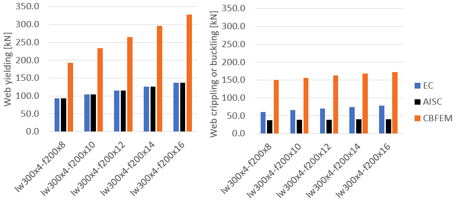
Figure. EC, AISC and CBFEM comparison yielding resistance and buckling or crippling resistance for varying flange thickness
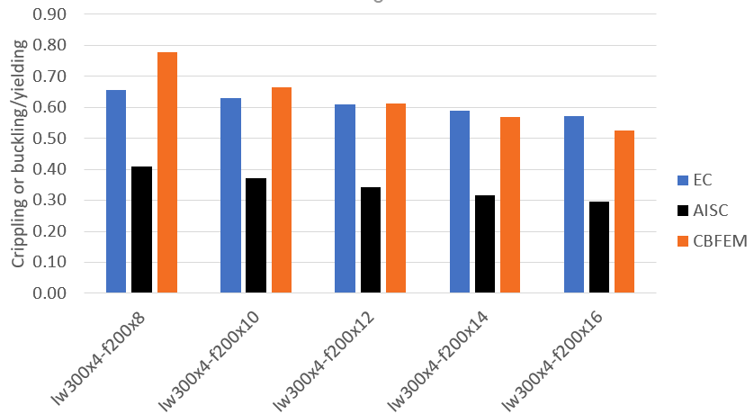
Figure. EC, AISC and CBFEM comparison of reduction factor due to buckling for varying flange thickness
Varying flange width
Cross-section properties are: web plate: (300 – tf)×4 mm, height 300 mm, flange thickness 12 mm. Flange width varies from 100 to 300 mm. Amplitude of initial imperfection is h/200 = 1.5 mm.
The analytical approaches in codes do not take flange width into account at all. The stiffness of a flange varies with the flange width so the load resistance is affected in IDEA StatiCa. Yielding resistance (MNA) is more sensitive than crippling resistance (GMNIA).

Figure. EC, AISC and CBFEM comparison yielding resistance and buckling or crippling resistance for varying flange width

Figure. EC, AISC and CBFEM comparison of reduction factor due to buckling for varying flange width
Varying member height
Cross-section properties are: web plate: (h – tf)×4 mm, flange plates 200×12 mm. Member height varies from 200 to 400 mm. Amplitude of initial imperfection is h/200.
Surprisingly, resistances in both yielding and crippling by IDEA StatiCa rise with increasing member height although the elastic critical buckling resistance decreases (370 kN, 220 kN, and 160 kN for beam height 200 mm, 300 mm, and 400 mm, respectively). Perhaps this is the effect of mesh density - the smallest member has the densest mesh. Yielding resistance by both codes remains the same and crippling or buckling resistance decreases with increasing member height; for AISC code much more severely.
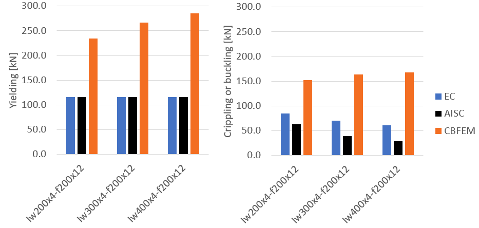
Figure. EC, AISC and CBFEM comparison yielding resistance and buckling or crippling resistance for varying member height
Effect of end-plate thickness
In Eurocode, the spreading angle through end plate is 1:1. The spreading angle is not explicitly mentioned in AISC 360-16. According to AISC Design Guide 4, the spreading angle through end plate is 1:1 as well. The difference is in fillet welds. Eurocode assumes leg size instead of throat thickness in AISC Design Guide 4.
Effect of end-plate thickness is investigated for a member with cross-section IPE 400 made of steel grade S275. End plates have sufficient overlaps to allow the spreading of load. Plate thickness inducing compression in the member is 20 mm and its weld throat thickness is 8 mm. In IDEA StatiCa models, double mesh density was chosen because the beam cross-section is quite large.

Figure. Model for end-plate connection, LBA - displacements, GMNIA - plastic strain
IDEA StatiCa shows higher increase in both yielding (MNA) and buckling (GMNIA) resistance than both codes, although the critical buckling load by LBA remains quite similar (1260 kN, 1270 kN, 1330 kN, 1390 kN for no end plate, tp = 10 mm, tp = 20 mm, tp = 30 mm, respectively).

Figure. EC, AISC and CBFEM comparison yielding resistance and buckling or crippling resistance for varying end-plate thickness
Solid element models in ANSYS
Investigation of local buckling
Due to big differences between CBFEM consisting of shell elements and EC and AISC, a solid element model of IPE 400 was created in ANSYS Workbench 2021 R2. Meshes of upper and lower plate and IPE 400 section are directly merged. The bottom of lower plate is fixed (DX, DY, DZ, RX, RY, RZ are all restrained); the top of upper plate is loaded in Y (vertical) direction and all other degrees of freedom are restrained (DX, DZ, RX, RY, RZ). The model is loaded by a force of 450 kN. The model consists of 80 thousand solid elements. Multizone meshing is used to achieve only hexa elements in the entire model. Basic size of element side is 5 mm. Steel with bilinear material diagram, modulus of elasticity 210 GPa, Poisson ratio 0.3, yield strength 275 MPa and slope of plastic branch 210 MPa is used.
Similarly to IDEA StatiCa, three analysis types are solved:
- Static Structural: Materially nonlinear analysis with small deformations
- Eigenvalue Buckling analysis
- Static Structural: Materially nonlinear analysis with large deformations and imperfections
Imperfections are included by updating mesh for the third analysis by the shape of the first eigenvalue modeshape with amplitude e0 = 2 mm.
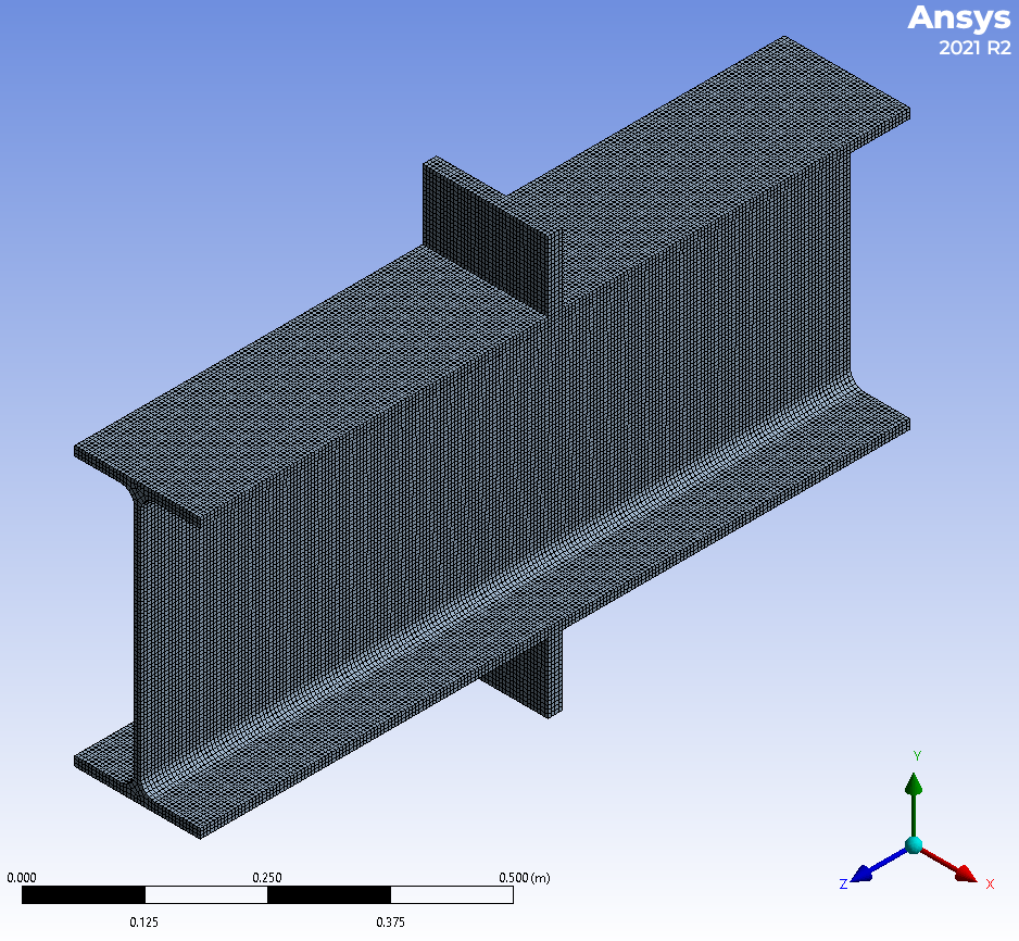
Figure. Meshed model in ANSYS

Figure. Deformations of GMNIA

Figure. Plastic strain concentrated in the web near upper and lower plate
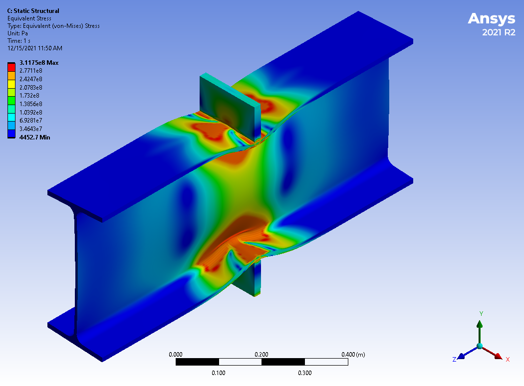
Figure. Von Mises stress
The results from IDEA StatiCa shell model were:
- MNA - FRd = 406 kN
- LBA - Fcr = 1260 kN
- GMNIA - FRd = 406 kN
Eurocode results were 455.3 kN for web yielding and 367.0 kN for web crippling. AISC results were 455.3 kN for web yielding, 454.7 kN for web crippling, and 315.4 kN for web buckling.
The results from ANSYS model consisting of solid elements with fine mesh are:
- MNA - FRd = 448 kN
- LBA - Fcr = 1040 kN
- GMNIA - FRd = 450 kN
For both MNA and GMNIA, 5% plastic strain was reached, and the load was still slightly increasing. There is almost no difference between analysis with small (MNA) and large (GMNIA) deformations. Surprisingly, the plastic strain rises a little bit faster for MNA.

ANSYS model confirmed that there is no reduction due to local buckling. This is the same result as the one provided by IDEA StatiCa shell element model. Eurocode and AISC predict 20% and 31% reduction due to buckling, respectively.
Investigation of the influence of fillet radius
IDEA StatiCa models show much higher resistance than codes for cross-sections with small radius of fillet between web and flange. Codes assume that for the determination of effective width the spreading angle is the same (2.5 : 1) through the member flange and the whole fillet. A model of IPE 400 without fillets was created to observe the effect of fillets. Apart from the fillet radius, the models including materials and boundary conditions are completely the same.
Comparison to experimental results for European column profiles
Experimental results were taken from De Mita (2008) where cross-sections HEA200–HEA300 and HEB200–300 are tested, 12 specimens altogether. All specimens were made of steel grade S275. Specimens were compressed by knife-edge bearings from both sides. The results of initial stiffness Sini, load resistance at the end of linear part of load-deformation curve Fp,exp, and ultimate load resistance Fu,exp are observed.
IDEA StatiCa Connection application is used with default mesh settings and with double mesh density. EPS analysis type with a stop at limit strain feature is used to determine ultimate load resistance and ST analysis type to determine initial stiffness.

Figure 7. Comparison of IDEA StatiCa, EC, and AISC to experimental results
The results of IDEA StatiCa are close to these of Eurocode and AISC and experimental results are much higher than both IDEA StatiCa and code results, so there is a sufficient margin of safety.
Web crippling has the same resistance as web yielding according to EC3 and AISC for HEB cross-section type. The load resistance for HEA cross-section type is affected by crippling up to 12% according to EC3 and AISC. IDEA StatiCa shows minimum \(\alpha_{cr}=3.88 > 3.0\), which means there should be no reduction in load resistance due to buckling yet. GMNIA calculations with IDEA StatiCa Member show almost no decrease in resistance, at the maximum only 2%.

Figure 10. Buckling factor \(\alpha_{cr}\) determined by IDEA StatiCa compared to buckling reduction factor by EC3 and AISC
There is a strong mesh sensitivity. The resistance of models with default settings (8 elements per member web or flange) compared to double mesh density (16 elements) is on average by 18% higher. Mesh sensitivity is further investigated in the following figure on the model with HEB300. Load resistance decreases with increasing mesh density.

Figure. Mesh sensitivity of a model of HEB300.
Initial stiffness of IDEA StatiCa is determined by secant stiffness at 2/3 of ultimate load resistance with default mesh settings. Experimental stiffness and Eurocode stiffness were taken from De Mita (2008). The stiffness of the load test system was subtracted in the paper and also the stiffness of members is subtracted in IDEA StatiCa.

Figure 9. Comparison of initial stiffness - Experiment, IDEA StatiCa, and Eurocode EN 1993-1-8
Initial stiffness determined by EC3 is on average 87% higher than experimental initial stiffness. IDEA StatiCa results are much closer; the numerical models are on average 12% stiffer.
Summary
References
L. De Mita, V. Piluso, G. Rizzano, Theoretical and Experimental Analysis of Column Web in Compression, The Open Construction and Building Technology Journal, 2008, 2, 294-303. Available at: https://openconstructionbuildingtechnologyjournal.com/VOLUME/2/PAGE/313/ABSTRACT/